
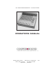
Operator`s manual
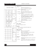

Left Section
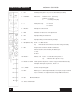
1. CH : Channel Power (down = on) Do not switch during recording.
2. PH / T : Phantom Power, ‘T’ power (AB). (phantom power is normally 48v, see layout A
to change to 12v).
3. Mic Pwr : Turns on mic power (down = on).
Mic power type selected by the switch above.
4. ø : N = normal, R = reverse. Audio phase only.
5. Mic / Line : Microphone or line level in.
6. Pad : Attenuator to reduce either mic or line input levels.
7. HP1 : High pass filter, pre-transformer.
8. HP2 : High pass filter, post transformer & preAmps.
9. EQ : Equalizer bypass. Affects HF, MF & LF filters, not HP filters.
10. AB : Assigns channel to AB mix busses.
Further selection is made by the pan pot. A = L, B = R.
11. CD : Assigns channel to CD mix busses.
Further selection is made by the pan pot. C = L, D = R.
12. Lim : The limiter is a symmetrical peak detecting type & is completely out of circut
when switched off. Threshold: See (14). Attack & release times are preset
internally (see layout A to change).
13. PFL : Pre-fade listen.
Sends selected channel to phones 1 only.
(Cuts out all other inputs to phones).
Can be changed to AFL (see layout A).
14. Thres : Limiter threshold. Clockwise = lower threshold.
15. O / L : Near overload or limiter threshold indicator (see layout A).
INPUT MODULE
MODEL CS 208
1
Left Page
Left Page