
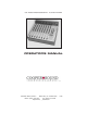
Operator`s manual
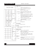
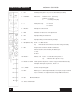

PIN OUTS
MODEL CS 208
6
All XLR’s are wired pin 2 high and are
transformer balanced.
Insert
1/4” stereo jack Tip = Send
Ring = Return
Sleeve = Ground
or direct out, pre-fader
(see app. note AN 2A & 2B)
Direct Out
(post-fader)
1/4” mono jack Tip = Signal
Sleeve = Ground
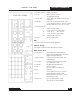
Mix Bus In
DB9 1 = Ground
2 = D
3 = C
4 = A
5 = B
(current input, see specifications)
Outputs
DB9 1 = Ground
2 = A
3 = B
4 = C
5 = D
TQG 3M
Pin 1 = Ground
Pin 2 = Signal
Pin 3 = N/C
TQG 5M
(roll) (See application note AN 1)
Pin1 = -10 v (Nagra)
Pin 2 = Stop (Nagra)
Pin 3 = Pause/Stop (DATs)
Pin 4 = Common (DATs)
Pin 5 = Record (DATs)
XLR 3M
Pin 1 = Ground
Pin 2 = High
Pin 3 = Low
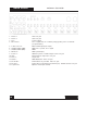
Phones 1, 2, 3
1/4” stereo jack (max load = 25! per channel)
Tip = Left
Ring = Right
Sleeve = Ground
Comm. In
1/4” stereo jack
Tip = High
Ring = Low
Sleeve = Ground
(See application note AN 3 for multiple inputs)
Returns
1/4” stereo jack
Tip = High
Ring = Low
Sleeve = Ground
Ext. Slate In
1/4” mono/stereo jack
Tip = Signal
Ring & Sleeve = Ground
Right Page
Right Page