
Operator`s manual
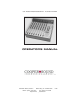

CSST-STERE0 MODULE
MODEL CS 208
7
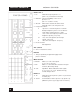
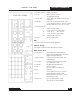
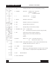
1. CH. Channel power (down = on). Do not switch during recording.
2. PH/DYN/T Mic Power - Phantom = 48v * (see notes).
Dynamic = no power.
T = tonader power (AB).
3. ø Audio phase only. N = normal.
R = reverse.
4. Mic/Line Microphone or line level in.
5. PAD Attenuator to reduce mic or line input levels.
6. HP1 High pass filter, pre-transformer.
7. HP2 High pass filter, post-transformer & pre-Amps.
8. Out (MS dec./LR) Down = no M/S decode.
Up = M/S decode to the mix busses & direct outs (post fader).
9. Mix Assigns stereo channel to the AB or CD busses.
Further selection can be made by the balance pot.
L = A,C.
R = B,D.
10. Monitor - MS dec. / LR Down = no M/S decode to phones 1.
Up = M/S decode to phones 1 only.
11. Monitor on & LED Sends signal to the phones 1 section only (see #10 for M/S decode).
Interrupts other inputs to phones 1, Down = on.
12. L, R Gain Controls mic pre-Amp gain.
13. BAL Balance pot - to either adjust the balance of 2 inputs, assign 1 channel
only to a mix bus or to adjust the stereo image width for M/S mics.
14. O/L Overload indicator.
15. Stereo channel fader
Left Page
Left Page