
User's Manual
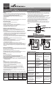


Single Location Control Installation (requires one Master dimmer)
Identify existing wiring (This switch will be a single-pole) and tag “Hot” wire. Use
voltage tester as necessary to confirm “Hot” wire (Voltage will be present at the
“Hot” wire when the lights are off).
Disconnect existing switch and remove.
Connect master dimmer as shown by connecting black
wire of dimmer to tagged “Hot” wire. Red wire must
be connected to the wire that goes to the light.
Gently push dimmer into place and secure with mounting screws. Make
sure disconnect switch at bottom of master is fully pushed in
Black
Red
Hot
Neutral
120V
Light Fixture
Green
Ground
MASTER
DIMMER
White
White
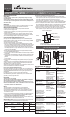
Two Location Control Installation (requires one Master and one Accessory)
Identify existing wiring (both existing switches will be “3-way”)
Tag common wire on both 3-Way switches (see “How to Identify
Common Wires” section
*
)
NOTE: The Circuit Breaker must be turned “ON” during this step
and the switches must be set so that the light is OFF. Ensure
that all wires are safely separated before turning the Circuit
Breaker “ON.” Connect the tester between the tagged common
terminal and ground in one of the boxes to determine the location
for the Accessory Dimmer. If the test indicates voltage then that
will be Location A, and will be used for the Accessory Dimmer.
If voltage is not present then the other 3-way location will be
Location A. NOTE: Disconnect power after this step.
Disconnect existing switch and remove. Connect
Accessory Dimmer in Location A as shown.
Red
Black
Hot
Neutral
120V
Light Fixture
Green
Ground
Green
Ground
White WhiteWhite
Red
White
Black
Traveler Wires
Black
ACCESSORY
DIMMER
MASTER
DIMMER
LOCATION A
Three Location Control Installation (requires one Master and two Accessory dimmers)
Identify existing wiring (4-way switches) Tag common
wire on 4-Way switch. (see “How to Identify Common
Wires” section
*
)
Connect the second Accessory Dimmer (4-way switch) as shown.
IMPORTANT! How to identify Common Wires
*
Two location:
Each switch will have insulated wires connected to three terminal screws plus a
green or bare wire connected to a green terminal screw. The three terminals are
usually one dark colored screw and two light colored screws (ignore the Green
screw). Alternatively, the three screws may be the same color and one will be
marked COMMON or COM Find the wires connected to the dark or COMMON
screws. Usually these wires are black but may be red or blue. Tag these wires on
both switches to identify when wiring.
Three location:
Two of the existing switches will be 3-way. The 3-way switches will be located
at each end of the circuit with a 4-way switch in between. TAG the two 3-way
switches as in the Two Location Control section. The 4-Way switch has 4 insu-
lated wires connected to 4 terminal screws. VERY IMPORTANT - TAG two same
color insulated wires, which are connected to screws of opposite colors.
Refer to 1.4 to push dimmers into place.
COOPER WIRING DEVICES LIMITED 2 YEAR WARRANTY
Cooper Wiring Devices (CWD) warrants its RF Smart Dimmer System to be free of defects in materials and workmanship in normal use and service for a period of two years from date of original purchase. THIS TWO (2) YEAR
LIMITED WARRANTY IS IN LIEU OF ALL OTHER WARRANTIES, OBLIGATIONS, OR LIABILITIES, EXPRESSED OR IMPLIED (INCLUDING ANY IMPLIED WARRANTY OF MERCHANTABILITY OR FITNESS FOR A PARTICULAR
PURPOSE THAT IS IN DURATION IN EXCESS OF TWO YEARS FROM THE DATE OF ORIGINAL CONSUMER PURCHASE). NO AGENT, REPRESENTATIVE, OR EMPLOYEE OF CWD HAS AUTHORITY TO INCREASE OR ALTER THE
OBLIGATIONS OF CWD UNDER THIS WARRANTY.
To obtain warranty service for any properly installed CWD RF Smart Dimmer System that proves defective in normal use send the defective RF Smart Dimmer System prepaid and insured to Quality Control Dept., Cooper Wiring
Devices, 203 Cooper Circle, Peachtree City, GA 30269; in Canada: Cooper Wiring Devices, 5925 McLaughlin Road, Mississauga, Ontario L5R 1B8.
CWD will repair or replace the defective unit, at its option. CWD will not be responsible under this warranty if examination shows that the defective condition of the unit was caused by misuse, abuse, improper installation,
alteration, improper maintenance or repair of damage in shipment to CWD.
CWD SHALL HAVE NO RESPONSIBILITY FOR INSTALLATION OF THE RF SMART DIMMER SYSTEM, OR FOR ANY PERSONAL INJURY, PROPERTY DAMAGE, OR ANY SPECIAL, INCIDENTAL, CONTINGENT, OR CONSEQUEN-
TIAL DAMAGES OF ANY KIND, RESULTING FROM DEFECTS IN THE RF SMART DIMMER SYSTEM OR FOR BREACH OF ANY EXPRESS OR IMPLIED WARRANTY ON THIS PRODUCT.
THE EXCLUSIVE REMEDY FOR BREACH OF THE LIMITED WARRANTY CONTAINED HEREIN IS THE REPAIR OR REPLACEMENT OF THE DEFECTIVE PRODUCT AT CWD’S OPTION. IMPLIED WARRANTIES (IF ANY) INCLUDING,
BUT NOT LIMITED TO IMPLIED WARRANTIES OF FITNESS FOR A PARTICULAR PURPOSE AND MERCHANTABIITY, ARE LIMITED IN DURATION TO A PERIOD ENDING TWO YEARS FROM THE DATE OF ORIGINAL CONSUMER
PURCHASE. IN NO CASE SHALL CWD’S LIABILITY UNDER ANY OTHER REMEDY PRESCRIBED BY LAW EXCEED THE PURCHASE PRICE. Some states do not allow the exclusion or limitation of incidental or consequential dam-
ages or allow disclaimers or modifications of or limitations on how long an implied warranty lasts, so the above limitations may not apply to you. Some Canadian provinces do not allow exclusion or variance of implied warranties
so that some or all of the above limitations may not apply to you. This warranty gives you specific legal rights and you may also have other rights which vary from state to state and province to province.
Read enclosed instructions carefully. If you have any questions concerning use or care of this product, please write: Consumer Service Division, Cooper Wiring Devices, 203 Cooper Circle, Peachtree City, GA 30269.
Black
1.3
White
Black
Bare
1.1
1.4
1.2
1.5
Master
Black
Black
Green
Red
Black
White
White
1.3
1.6
TOP
1.4
2.1
Black
Bare
Black
Red
Tag
White
2.1
2.2
Black
Bare
Black
Red
Tag
White
2.2
Green
Red
Tag
Black
2.4
Accessory
ACCESSORY
White
Black
LOCATION A
ACCESSORY
White
2.3
2.5
Master
Red
Green
White
Black
Black
Tag
Black
Red
MASTER
DIMMER
White
2.4
3.1
White
Black
Red
Red
Bare
Tag
Black
Tag
3.1
3.2
Accessory
White
Red
Black
Black
Green
ACCESSORY
White
Tag
4-Way Location
3.2
Tag
-
To Light
Tag
- Hot
Red
Black
Hot
Neutral
120V
Light Fixture
Green
Ground
Green
Ground
WhiteWhite
White
ACCESSORY
DIMMER
Red
White
Black
Traveler Wires
Green
Ground
White
WhiteWhite
Black
Red
Black
Traveler Wires
LOCATION A
ACCESSORY
DIMMER
MASTER
DIMMER