
Specification

d
. The sensor blue wire will connect to the red traveler wire in the wallbox
e
. The sensor green wire will connect to the ground wire in the wallbox.
f. Install the sensor loosely using the mounting screws provided.
2
. Remove the existing switch in the other 3-way location.
a. Connect the two black wires together.
b. Connect the white wires together and also connect the white wires to the common terminal
(
usually a black screw or a marking such as COM or COMMON near the terminal) on the 3-way switch.
c
. Connect the red wire to either of the other switch terminals.
d. Re-install the 3-way switch and tighten securely.
3
. Apply power and verify that the sensor works by pushing the ON/OFF button. The lights should turn ON and OFF.
I
f the lights do not work, then turn the power off and swap the connections to the sensor black and red wires.
4. Apply power again and verify the sensor works by pushing the ON/OFF button to verify the lights turn ON and OFF.
5. Turn power OFF and go to COMPLETING THE INSTALLATION.
F
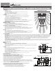
or 2 sensor applications, wire the sensor switches according to wiring diagram #3 using the wire nuts provided.
1. Remove the existing switch in the 3-way location where the first sensor will be installed.
a
. The sensor black wire will connect to the two black wires in the wallbox.
b
. The sensor red wire will connect to the red wire in the wall box.
c. The sensor white wire will connect to the neutral wire (white) in the wallbox.
d. The sensor blue wire is not used and should be capped off with a wire nut.
e
. The sensor green wire will connect to the ground wire in the wallbox.
f. Install the sensor loosely using the mounting screws provided.
2. Remove the existing switch in the other 3-way location where the second sensor will be
i
nstalled.
a
. The sensor black wire will connect to the black wire coming from the first wallbox.
b. The sensor red wire will connect to the red wire coming from the first wallbox and to the
black wire going to the light fixture.
c
. The sensor white wire will connect to the neutral wire (white) in the wallbox.
d. The sensor blue wire is not used and should be capped off with a wire nut.
e. The sensor green wire will connect to the ground wire in the wallbox.
f
. Install the sensor loosely using the mounting screws provided.
3
. Apply power and verify that the sensors work by pressing the ON/OFF buttons on each sensor.
The green LEDs on the sensors should turn on and off. If the LED does not work on either or both
sensors, you must swap the red and black sensor wire on that sensor.
4
. Re-install the sensor loosely, apply power again, and verify the sensor works by pushing the
ON/OFF button to verify the green LEDs and the lights turn ON and OFF.
5. Turn power OFF and go to COMPLETING THE INSTALLATION.
C
OMPLETING THE INSTALLATION:
1. Secure sensor into the wall box using two mounting screws provided. Turn the circuit breaker ON.
2. Allow the sensor to stabilize for 10 seconds. The sensor is now ready to detect motion.
3. Verify that Power in ON by pushing the ON/OFF button. Lights and LED should turn ON.
4. NOTE - The sensor time delay is factory preset (OS310U = 5 minutes; VS310U = 30 minutes).
5. If you want to change the time delay proceed as follows:
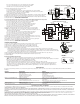
a. Remove the button from the sensor by pressing in the hooks on the button, and then lift up on the button as shown in Fig. 4.
b. Set the time delay using the dial on the right side by using a small Phillips screwdriver. Align the arrow on the dial to desired time delay.
c. To allow the installer to quickly confirm that the second is functioning properly the time delay can be set to TEST. This will set a time delay
of 5 seconds, which allows quick feedback that the sensor is working properly.
6. Replace push button by sliding it upward into the slots in the front housing and push down until the button hook snaps into place.
7. Push the ON/OFF button to verify that the lights turn ON/OFF, and that the button operates freely.
8. Install the wallplate.
Daylight Sensing Adjustment (OS310U only):
• The Daylight sensing feature prevents lights from turning ON when the room is adequately illuminated by natural light.
• NOTE - The factory setting for this adjustment is fully clockwise and permits motion detection to turn ON the lights regardless of the ambient
light level in the room. If the Night Light is ON the daylight feature is disabled.
• Remove the ON/OFF pushbutton to access the light level adjustment. See Fig. 5.
• This adjustment must be made when the light level in the room is at the desired level for the lights to turn ON.
• From the clockwise position, turn the dial on the left counterclockwise using a small Phillips screwdriver until the Night Light turns ON.
• Step away from the sensor to allow the device to calibrate to the normal light level in the room. Do not obstruct the natural light. The
calibration process starts when the Night Light turns OFF, and will take approximatly 5 seconds. After completition the lights will turn on.
• Replace the ON/OFF pushbutton.
TROUBLESHOOTING:
If you have a problem with your Motion Sensor, first follow this guide. If the problem persists, call the customer service hotline at 1-866-853-4293 between 8:00 A.M. and 6:00 P.M. EST
weekdays.
SYMPTOM POSSIBLE CAUSE SOLUTION
Light does not automatically turn on. 1. Circuit breaker is turned off, or fuse is blown. 1. Turn circuit breaker on, or replace fuse.
2. Bulb is defective. 2. Replace light bulb.
3. Poor connection. 3. Verify all wiring connections.
4. Control may be wired incorrectly. 4. Check wiring.
5. Daylight sensing prevents lights on 5. Re-adjust daylight sensing level.
6. Manual On mode selected 6. Set device to Automatic On mode.
Light does not automatically turn off. 1. Motion is still present. 1. Make sure there is no motion during the time delay period.
2. Time Delay has not expired. 2. No action needed or shorten TIME DELAY.
3. Control may be wired incorrectly. 3. Check wiring
4. Switch is being triggered by air vent or other heat source. 4. Move switch to the other switch location (if a 3-way), or determine the
source triggering the switch, and alter the air flow.
Light does not stay on 1. Motion is not detected. 1. Create movement in front of the sensor for 5 seconds.
2. TIME control is set for too short a delay 2. Set switch TIME control to longer time period.
Remote switch does not work 1. Control may be wired incorrectly. 1. Check wiring
COOPER WIRING DEVICES LIMITED 2 YEAR WARRANTY
Cooper Wiring Devices (CWD) warrants this device to be free of defects in materials and workmanship in normal use and service for a period of five years from date of original purchase. THIS 2 YEAR
LIMITED WARRANTY IS IN LIEU OF ALL OTHER WARRANTIES,
OBLIGATIONS, OR LIABILITIES, EXPRESSED OR IMPLIED (INCLUDING ANY IMPLIED WARRANTY OF MERCHANTABILITY OR FITNESS FOR A PARTICULAR PURPOSE THAT IS IN DURATION IN EXCESS OF 2
YEARS FROM THE DATE OF ORIGINAL CONSUMER PURCHASE). NO AGENT, REPRESENTATIVE, OR EMPLOYEE OF CWD HAS AUTHORITY TO INCREASE OR ALTER THE OBLIGATIONS OF CWD UNDER THIS
WARRANTY.
To obtain warranty service for any properly installed CWD device that proves defective in normal use send the defective RF System prepaid and insured to Quality Control Dept., Cooper Wiring Devices, 203
Cooper Circle, Peachtree City, GA 30269; in Canada: Cooper Wiring Devices, 5925 McLaughlin Road, Mississauga, Ontario L5R 1B8.
CWD will repair or replace the defective unit, at its option. CWD will not be responsible under this warranty if examination shows that the defective condition of the unit was caused by misuse, abuse,
improper installation, alteration, improper maintenance or repair of damage in shipment to CWD.
CWD SHALL HAVE NO RESPONSIBILITY FOR INSTALLATION OF THE RF SYSTEM, OR FOR ANY PERSONAL INJURY, PROPERTY DAMAGE, OR ANY SPECIAL, INCIDENTAL, CONTINGENT, OR CONSEQUENTIAL
DAMAGES OF ANY KIND, RESULTING FROM DEFECTS IN THE RF SYSTEM OR FOR BREACH OF ANY EXPRESS OR IMPLIED WARRANTY ON THIS PRODUCT.
Hot
O
utput
Red
B
lue
3-Way Red Traveler
B
lack Traveler
Light Fixture
White
Neutral
Black
Hot
Neutral
Ground
BlackBlack
B
are Green
W
hiteWhite
F
irst Location
Second Location
White Traveler
3 traveler wires are required
DIAGRAM 2B: SENSOR IN LOCATION WITH HOT WIRE
3-Way
Switch
OS310U or
VS310U sensor
Neutral
First Location
Second Location
3 traveler wires are required
DIAGRAM 3: SENSORS IN BOTH LOCATIONS
OS310U or VS310U Sensor OS310U or S310U Sensor
Light Fixture
Red Traveler
B
lack Traveler
White Traveler
N
eutral
White
Neutral
White
Neutral
White
Neutral
W
hite
Neutral
G
round
Bare
G
round
Bare GreenGreen
3
-Way
Blue
3
-Way
Blue
O
utput
Red
H
ot
Black
Black
H
ot
Black
H
ot
Black
O
utput
R
ed
1. PRESS TO
RELEASE
HOOK
FIGURE 4
2. LIFT UP
BUTTON
LIGHT LEVEL
T
E
S
T
5
1
5
3
0
TIME DELAY
TURN TO SET
FIGURE 5: