TS690 & TS690ID Intruder Alarm Control Panels SYSTEM OPEN 17:30 01 Jan _ ~ A 1 2 3 B 4 5 6 C 7 8 9 D ENT 0 ESC Sett ing the Syst em E n t er y ou r pa s s c o de X X X X th en l ea v e th e p r o tec t e d a re a. Unsetting the System G o di r e ct ly to t h e k e yp ad an d en te r y ou r p as s c o d e X X X X . Resetting E n t er y ou r pa s s c o de X X X X f o ll ow e d by E N T the n 3 . Te l eph o n e y o u r a l ar m c o m pan y a nd fo ll o w th ei r i ns tr uc t io ns .
TS690 & TS690ID Installation Manual Contents Overview Introduction . . . . . . . . . . . . . . . . . . . . . . . . . 4 Control Panel . . . . . . . . . . . . . . . . . . . . . . . . 4 Remote Keypads . . . . . . . . . . . . . . . . . . . . . 4 32 Character LCD (NETLCD) . . . . . . . . . . . 4 8 Character Starburst (NETSTAR) . . . . . . . . 4 4 Character LED (NETLED) . . . . . . . . . . . . . 4 Remote Arming Station (NETARM) . . . . . . . 4 Proximity Reader (TSNETPROX) . . . . . . . . . . 4 TS700 LEC . . . .
TS690 & TS690ID Installation Manual Add/Clear ID Devices (TS690ID) . . . . . . . . . . 39 Clear & Relearn ID Devices . . . . . . . . . . . 39 Add ID Devices . . . . . . . . . . . . . . . . . . . . . 39 Display Codes . . . . . . . . . . . . . . . . . . . . . 39 Slow Scan Mode. . . . . . . . . . . . . . . . . . . . 39 View Location Text (LCD Only). . . . . . . . . . . . 40 Re-Map ID Devices (TS690ID) . . . . . . . . . . . . 40 Relearn Hardware. . . . . . . . . . . . . . . . . . . . .
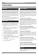
Overview TS690 & TS690ID Installation Manual Overview Introduction Remote Keypads The TS690 range of alarm control systems have been designed to suit small to medium installation sites. The TS690 system can monitor 6 zones locally and up to 8 zones via remote keypads or LECs. All zones can be wired either as double pole or end of line. The TS690ID system can monitor up to 30 zones via ID biscuits and 8 conventional zones via remote keypads or LECs.
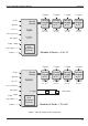
TS690 & TS690ID Installation Manual Printer Speaker Aux 12V Remote Network TS690 Overview 1 Output 1 Output 1 Output 1 Output Remote Keypad or LEC Remote Keypad or LEC Remote Keypad or LEC Remote Keypad or LEC 2 Zones 2 Zones 2 Zones 2 Zones (DP / EOL) (DP / EOL) (DP / EOL) (DP / EOL) DCI Connection 6 Zones Bell output (DP / EOL) Strobe output Digi outputs 1- 5 DC6 Digi Modem (Optional) Outputs 1- 3 Printer Remote Network Speaker Aux 12V TS690ID Number of Zones = 8 to 14 1 Ou
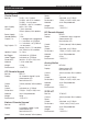
Overview TS690 & TS690ID Installation Manual System Architecture Specifications Control Panel Part No.: Input Supply: Current: Power Supply: Standby Battery: Outputs 1-3: Digi Outputs 1-5: Speaker Output: Bell Trigger: Strobe Trigger: Dimensions: Material: Weight: Environment: TS690 - 6 to 14 zones TS690M - with DC6 modem TS690ID - 2 to 38 zones TS690IDM - with DC6 modem 230V ±10% 50Hz 110mA (normal) 250mA (alarm) with speaker 1.5A 7.
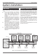
TS690 & TS690ID Installation Manual System Installation System Installation Cable Routing Remote/LEC Network Wiring When installing cables, the following should be noted: The Remote Network connections are used for connecting either remote keypads or LECs. Each device has 5 connection terminals and therefore a 6 core cable is required for interconnection. It is recommended that the spare core is doubled up with the [B] connection as this will help reduce voltage drop on long cable runs.
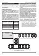
System Installation TS690 & TS690ID Installation Manual ID Loop Wiring (TS690ID Only) Each ID device is connected across a two-wire ID loop. Apart from observing the correct polarity, any wiring configuration can be used, as shown in the figure below. Cabling Requirements The ID loop can be wired using standard 4 core cable, this allows 2 cores to be used for the ID devices and 2 cores for supplying 12V power for PIR's etc.
TS690 & TS690ID Installation Manual System Installation Control Panel Installation Proceed as follows: 1. Open the control panel by removing two screws from the front cover. Remove the cover and disconnect the earth bonding cable from the spade connection near the transformer. 2. Note the position of the cable entries as follows: 4. Screw a No 10 screw into the plugged hole. Reposition the back box and mark the remaining two securing holes. Remove the back box, drill and plug the holes. 5.
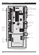
System Installation TS690 & TS690ID Installation Manual Control Panel PCB Layout N/O N/CCOM LED2 Z1 T1 CIRCUIT 1 POWER ON AUX +3 -2 JP1 DIGI-MODEM JP3 FACTORY RESET Z2 T2 CIRCUIT 2 JP5 U3 REM LINE + 1 2 3 4 5 RESET FLT DC + PWR DIGITAL COMMUNICATOR - 1 AMP JP2 REMOTE KEYPAD ENGINEERS REMOTE A B C D E REMOTE NETWORK Remote keypad Network connections (SELV) PRINTER 0V 12V OUTPUTS OUTPUT 1 FS3 Panel Outputs O/P 1 = Change over contacts O/P 2 = Switched -ve @ 500mA O/P 3 = Switched +ve
TS690 & TS690ID Installation Manual Connection Terminals & Indicators Connection terminals on the TS690 / TS690ID are described as ether “Safety Extra-Low Voltage” (SELV) circuits or “Telecommunication Network Voltages” (TNV) circuits. Figure 5 shows the two types of circuits. JP1 PRINTER This 6-pin plug is used for connecting to either a CPA6.P printer or a standard RS232 printer via the MPA/DCI printer adapter.
System Installation TS690 & TS690ID Installation Manual Mains Connection NETSTAR Remote Keypad The mains supply is connected to a 3 way “Euro Type” fused terminal block, which is fitted with a 315mA fuse. All electrical connections should be carried out by a qualified electrician and must comply with the current IEE regulations. The NETSTAR remote keypad has a 8 character backlit Starburst Liquid Crystal Display (LCD).
TS690 & TS690ID Installation Manual System Installation Network Connections & O/P. Terminals A to E are used to connect the remote keypad to the control panel network . T he O/P te rmi nal is the programmable output. + 9 Tamper Switch. Remote Keypad case tamper 10 Proximity Reader Option. Pins for plugging on a TSNETPROX proximity reader module. 1.
System Installation TS690 & TS690ID Installation Manual 5. Set the “ENT KEY DISABLE” jumper link to the required position. 6. Set the “WARD SOUNDER CONTROL” jumper link to the required position. 7. Finally clip the remote keypad cover onto the base being careful not to trap any cables or to obstruct the tamper switch. TS700 LEC Installation The TS700 LEC (Local Expansion Card) is connected to the “Remote Network” and provides two additional programmable detection circuits and a programmable output.
TS690 & TS690ID Installation Manual System Installation 4. Connect “Remote Network” cables and detection circuit cables to the appropriate terminals, see Figure 10 l Normally open devices such as pressure pads and exit terminator buttons are connected between the zone and tamper terminals. 5. Set the I/D selector jumper link to the required position: l If the detection circuit is not used links can be fitted across the zone and tamper loops or programmed as Not Used.
System Installation TS690 & TS690ID Installation Manual 500 metres or 100 Ohms 4K7 Alarm CIRCUIT B TB ZB 4K7 = Yellow, Violet, Red 2K2 = Red, Red, Red 2K2 Tamper When the tamper switch is opened, the ID biscuit becomes off line and a tamper alarm is generated by the control panel. If the alarm contacts are opened the biscuit's internal sensor changes state and the control panel will see this as an active condition and will respond as appropriate.
TS690 & TS690ID Installation Manual System Installation Wiring a Biscuit to a Panic Button External Sounder Connections The figure below shows typical wiring configuration for a standard panic button. The following terminals have been provided to allow connections to an external sounder: H/O - This is used to provide a permanent -ve hold off to external sounders, strobes etc. H/O + This is used to provide a permanent +ve hold off to external sounders, strobes etc.
System Installation TS690 & TS690ID Installation Manual Extension Loudspeakers Up to two extension loudspeakers can be connected across the [SPK+] and [H/O-] terminals on the control panel PCB. The volume for the loudspeaker is controlled by VR1 “Speaker Volume”. SPK+ H/O - REM RESET If the system is programmed for “Engineer Reset”, then after a full alarm the system will require resetting, normally this is done by the engineer or coded remote reset.
TS690 & TS690ID Installation Manual Application The DC6 digital communicator/modem is suitable for connection to the following types of telephone line: l + + + Direct exchange lines (PSTN) supporting DTMF (Tone dialling) or Loop Disconnect (Pulse Dialling). PABX exchanges (with or without secondary proceed indication). The DC6 is only approved for use with compatible PABXs. Correct operation in all circumstances is not guaranteed.
System Installation + Installation For your safety, installation of the DC6 MUST be carried out in the sequence shown below: 1. Ensure that all power is removed from the system i.e. mains supply and standby battery. 2. Remove the DC6 from its packaging and fit the plastic mounting pillars into the 4 holes provided. 3. Align the DC6 with the connector JP4 on the main PCB and push firmly into place. 4. Connections to the telephone network must be made via a NET master socket (Line Box).
TS690 & TS690ID Installation Manual System Installation Connecting a Printer Using the CPA6 Printer The TS690 and TS690ID supports two type of printers, the CPA6 printer (no longer available) and any standard RS232 printer. When using an RS232 printer a DCI/MPA printer adaptor will be required. Menvier Security supply a DATAC printer kit which consists of a portable RS232 printer, charger unit and DCI adapter. 6. Plug the CPA6 printer directly on to the PRINTER plug (JP1) on the main control panel PCB.
System Installation TS690 & TS690ID Installation Manual +ve O/P (Programmed as Alarm / Bell / etc) Diode (IN4001) Relay Aux 0V + 12 V Relay available from RS components P/No. 351-982. Capable of switching mains voltages Aux 12 V Diode (IN4001) Relay -ve O/P (Programmed as Alarm / Bell / etc) + 12 V 0V Relay available from RS components P/No. 351-982.
TS690 & TS690ID Installation Manual System Installation 3. With the ID loop still disconnected from the control panel, use a DVM to measure the resistance between the following cores and terminals: (a) ID + core and 0V terminal. (b) ID + core and +12V terminal. (c) ID + core and Mains earth terminal. Initial Power-Up To power the system for the first time: 1. Place a small screwdriver blade between the pins on the control panel PCB, marked “FACTORY RESET”.
System Installation TS690 & TS690ID Installation Manual NVM Defaults Section User Codes Option Digicom Channels System Timers System Timers Setting Modes 24 Rem Reset Option Default 004 5678 00: Bell is an SAB Yes Walk Test 01: User 1 Limited No Courtesy Light 02: Fire Signals All No Switch 12V 03: Silent 24hr Ccts No Code Accepted 04: Enable Duress No 1234 User 01 Master Panel Output 1 Panel Output 5 Section Algorithm User 00 Engineer Panel Output 2 Panel Outputs Panel Outp
TS690 & TS690ID Installation Manual Engineer’s Menu 1 Engineer’s Menu 1 Introduction Engineers menu 1 is the first of two engineers menus, which is selected when the engineer’s passcode is entered. The engineer may leave “Engineer menu 1" by pressing the [ESC] key. The system will return to the unset condition but the remote keypads will show ”Engineer-on-site". This message will be cleared the next time a valid user passcode is entered or by exiting the engineer's mode via user menu 1.
Engineer’s Menu 1 TS690 & TS690ID Installation Manual Panel Outputs [1.1] Outputs 1-3 on the control panel and remote keypad outputs 5-8 can be programmed to any of the output types shown on pages 26 to 29. Digicom Channels The 8 plug-on digicom channels can be programmed to any of the output types shown on pages 26 to 29. Starburst LED LCD Engineers menu 1 Select Options :- ENGR 1 - LCD Engineers menu 1 Select Options :- E1 - 1 PANEL - Digi Channel ? Enter Number > - PAN.- Enter output No.
TS690 & TS690ID Installation Manual No Type/Description 004 Walk Test Activates when the "Walk Test" option is selected and deactivates when the "Walk Test" option is finished. 005 Alarm Activates when an intruder alarm is detected and deactivates when the alarm is reset or aborted. 006 P.A. Activates when a PA alarm is detected and deactivates when the alarm is reset. 007 Fire Activates when a Fire alarm is detected and deactivates when the alarm is reset.
Engineer’s Menu 1 No Type/Description TS690 & TS690ID Installation Manual No Type/Description 032 Duress Alarm Activates when a duress passcode is entered and deactivates when the duress alarm is reset. 044 General Fault Activates during battery fault or when the system is prevented from being set. Deactivates when all faults are cleared. 033 System Part Set Activates when the system is part set and deactivates when the system is fully set or unset.
TS690 & TS690ID Installation Manual Engineer’s Menu 1 and the circuit remains active until the end of the confirmation time then the control panel omits the active zone and triggers the Active Omit output. The control panel deactivates the output when a user disarms the system. Use existing output type 036 = System Open to indicate Unset Complete. 100 - 137 Circuit Mimic Will mimic (active when circuit is active) circuits 01 to 38 respectively.
Engineer’s Menu 1 TS690 & TS690ID Installation Manual [7] Inverted - Inverts the operation of the keyswitch. The “Omit” attribute can only be assigned to Night, 24hr, and Auxiliary circuit types. If the “Keyswitch” is not assigned to any of the above options, the circuit becomes a “Monitored” circuit. A “Monitored” circuit is monitored at all times. When triggered it will activate any outputs that are programmed as Timed Output and log the event.
TS690 & TS690ID Installation Manual Engineer’s Menu 1 Starburst LED LCD Engineers menu 1 Select Options :- ENGR 1 - E1 - CCT NO.-- CT.-- 4 Program circuits Enter CCT No.>-Enter circuit No. e.g. 04 ENT Circuit No. Circuit Type CCT 04 NIGHT NIGHT NITE Enter circuit type: 0 = Not Used 1 = Night 2 = 24hr 3 = PA Silent 4 = PA Audible 5 = Fire 6 = Auxiliary 7 = Final Exit 8 = Exit Terminator 9 = Key Point e.g. 7 for Final Exit ENT Attributes CCT 04 F.EXIT >* * * * * * * * 04 F.
Engineer’s Menu 1 06 Bell Duration This controls the duration of the external bell/sounder. If the timer is set to 199 the bell output is continuous. This timer has a working range of 000-199 minutes. (Default: 020 Mins) 07 Bell Delay This timer delays the activation of the external bell/sounder and internal sounders. This timer has a working range of 000-199 minutes. Note: Any alarm during the entry procedure will cancel the bell delay. (Default: 000 Mins) 08 2 Act.
TS690 & TS690ID Installation Manual Engineer’s Menu 1 19 Test Call If the system is fitted with a DC6, it is possible for the control panel to make the DC6 send a timed test call to the central station. The “Test Call” timer sets the period of activation, i.e., 000=Disabled, 001=daily, 007=weekly etc. Once programmed the digicom will send the test call at the hour defined by timer 23. This timer has a working range of 000-199 days.
Engineer’s Menu 1 TS690 & TS690ID Installation Manual LCD To set the system the user first enters their access code at a keypad or operates a keyswitch. The control unit starts the exit tone. Note that the exit time is infinite in this option. The user then operates the final exit zone and turns the key in the lock switch to “locked”. The system sets seven seconds after the lock switch contacts open. To unset the system the user turns the lock switch to “unlocked” (closing the lock switch contacts).
TS690 & TS690ID Installation Manual Engineer’s Menu 1 Remote Reset Algorithm [1.8] When the system is programmed for “Engineer Reset” the requirement to send an engineer to site can be overridden by the user by using the “Remote Reset” facility. If an alarm is generated the system will respond with a four digit “seed” code which the user quotes to the Alarm Receiving Centre or alarm company. The “seed” code is then entered into a decoder and a unique “Remote Reset” code is generated.
Engineer’s Menu 1 10 Tamp user reset When programmed as “Yes", tamper alarms can be reset by the user. When programmed as ”No", tamper alarms can only be reset by the engineer or via remote reset. (Default: Yes) 11 Do battery test When programmed as "Yes" the control panel battery and any monitored PSU batteries are tested every hour and when exiting the engineer's mode. When programmed as "No" the control panel battery and any monitored PSU batteries are not tested. (Default: No) 12 F.
TS690 & TS690ID Installation Manual Engineer’s Menu 1 25 Answer Phone Def When programmed as “Yes”, the plug-on digi-modem will only answer incoming calls after a second attempt. When programmed as “No”, the plug-on digi-modem will answer incoming calls after the modem ring counter has expired. (Default: No) 30 Sounder on Confirm When programmed as “Yes” the control unit activates the internal sounders after a confirmed alarm and any programmed bell delay.
Engineer’s Menu 1 34 Entry Keypad Lock When programmed as “Yes” then users cannot unset the system from a keypad during entry. Program this option as “Yes” if you are installing a DD243:2002 compliant system and the user must unset the system with a proximity detector (“Portable ACE”). The user must employ a proximity tag to disarm the system during the entry period. When programmed as “No” then users can unset the system from a keypad during entry. + If your make Pset Com. Dly (Eng 1.5.
TS690 & TS690ID Installation Manual Engineer’s Menu 1 Go to User Menu 1 [1.0] This option allows the engineer to access “User menu 1", the flowchart below shows the options within ”User menu 1", for full details refer to the "Operators Manual". [1.A] This option allows the engineer to add and remove ID devices from the system. It also allows you to diagnose the ID loop. Clear & Relearn ID Devices Engineers menu 1 Select Option :- 0 User menu 1 Select Option :ESC 1 Sounder.
Engineer’s Menu 1 TS690 & TS690ID Installation Manual LCD Engineers menu 1 Select Option :- ID Devices 01 - 15 16 - 30 Starburst LED ENGR 1 - E1 - USE 16x2 USE LCD A >HHHHHHHHAAHH... >............... CCT 01 Healthy Engineers menu 1 Select Options :- Starburst LED ENGR 1 - E1 - -- -- 18 18 21 21 C A = Add ID devices B = Toggle ID & View Circuits C = Clear & learn ID devices 0 = Toggle Slow Scan Mode B LCD Re-map Devices Enter Device >-Enter ID device No (01 - 30) e.g.
TS690 & TS690ID Installation Manual Engineer's Menu 2 Engineer's Menu 2 Introduction Engineer's menu 2 is selected by pressing the [ENT] key whilst Engineer's menu 1 is selected. Each menu option can be selected by pressing the relevant “Hot key”.
Engineer's Menu 2 TS690 & TS690ID Installation Manual View Circuits [2.1] Each detection circuit may be viewed to ascertain its status. The circuit status conditions and resistance are shown below: Set System Time [2.2] The system time is displayed in a 24hr format on all remote keypads and is also used to time stamp events in the system event log. Status Response Normal Min. Max. LCD Healthy None 2.2 KΩ 54 Ω 4.1KΩ Active Alarm 6.9 KΩ 4.
TS690 & TS690ID Installation Manual Change Passcode Engineer's Menu 2 [2.4] This option allows the engineer to change their passcode. The default passcode is 1234 but the installation engineer should change this to their own personal 4 digit passcode. LCD Engineers menu 2 Select Option :- Alter Shunt Group Circuits can be assigned to the shunt group. The shunt group can be isolated by using user menu 1 option 6 or by using a “Shunt” code see “User Manual”.
Engineer's Menu 2 TS690 & TS690ID Installation Manual Configure Part Sets [2.8] The TS690 and TS690ID can be configured to have up to three parts set modes (Part Set A, Part Set B and Part Set C). This option allows the engineer to configure each part set mode. Within each part set mode you must designate which circuits will remain armed and which circuits will be omitted.
TS690 & TS690ID Installation Manual Engineer's Menu 2 Log Event Codes LCD Starburst LED Description AC OFF A.C. OFF PF Mains power removed. AC RESTORED A.C. ON Pr Mains power restored ACTION ALARM ALM SENT AA Alarm activated when system is part-set. ALARM 01-38 ALARM 01-38 CA.01-38 Full alarm from circuit (01-38). AUX/BELL TAMPER AUX TAMP AT Auxiliary tamper activated. AUXILIARY 01-38 AUX 01-38 Au.01-38 Auxiliary circuit activated.
Engineer's Menu 2 TS690 & TS690ID Installation Manual Log Event Codes LCD Starburst LED Description PANEL LID TAMPER LID TAMP LT Control panel lid removed. PART SET A/B/C P.SET A/B/C PS.A/B/C System Part-Set using one of the A, B, or C buttons. PASSCODE 00-15 USER 00-15 Ur.00-15 User passcode entered. (00-15). REINSTATEMENT Time and date for reinstatement. RELEARN REQUIRED RESET CONFIG. REST CON. Hardware relearn required see page 38. REM REMOVED 01-04 R. REM 01-04 rr.
TS690 & TS690ID Installation Manual Engineer's Menu 2 LCD Only LCD Engineers menu 2 Select Option :- Starburst LED ENGR 2 - Engineers menu 2 Select Option :- E2 - B A Call back No. Tel No. Call Number 1 0181 12345678 CALL NO.1 1-CCT, 2-Banner 3-Location No. 1 1 = Circuit Text 2 = Banner Message 3 = Panel Location Text 1 = Call No. 1 2 = Call No. 2 3 = Call No. 3 e.g.
Engineer's Menu 2 TS690 & TS690ID Installation Manual This option allows the Modem site number to be programmed. The “Modem Site No.” is a 4 digit number that is used as a site reference. When using the “Lineload” software the “Site Reference” number in the site profile must match the “Modem Site No.” that is stored in the control panel.
TS690 & TS690ID Installation Manual LCD Only Engineers menu 2 Select Option :- C Engineer's Menu 2 Digicom Tests This option allows the engineer to test each channel on the plug-on digi-modem (DC6) and the five digi outputs on the main PCB. Modem options Select Option :- LCD 6 Engineer menu 2 Select Option :- 018112345678 |elephone No. 1 C Enter telephone Number Modem options Select Option :- ENT 7 018112345679 |elephone No.
Engineer's Menu 2 TS690 & TS690ID Installation Manual Text Editing Keys Displaying Text on a Starburst When programming any text the keys on the keypad function as shown below: The TS790.STAR remote keypad is capable of displaying up to eight characters of text when it is connected to the TS690/TS690ID control panels. However the text can only be entered using a TS900 LCD remote keypad or via Lineload software.
TS690 & TS690ID Installation Manual Appendices Appendices Contact ID Extended Reporting Contact ID extended reporting is a new format which when used with the DC6 can be used to report circuit ID data, user ID etc. The central station alarm receiver must be capable of receiving “Contact ID extended Format” data.
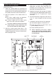
Appendices TS690 & TS690ID Installation Manual P 7 C Kitchen 6 C Dining Room 5 3 C Hall Garage CP Lounge 4 C RK 2 8 P P C 1 Key: P Passive Infra-Red Detector C Magnetic Contact P 9 Bathroom Bedroom 2 RK Remote Keypad CP Control Panel P 10 Landing RK Bedroom 1 Bedroom 3 Figure 27.
TS690 & TS690ID Installation Manual Appendices Part-Set Application Example Alarm Abort & Confirmation This application example shows how to configure the part set buttons to set different areas of a 3 bedroom house. Both the TS690 and TS690ID support “Alarm Abort” and “Sequential Confirmation”. The alarm abort can be achieved by either sending an abort signal on a dedicated channel or by restoring the alarm channel.
Appendices TS690 & TS690ID Installation Manual feature can be disabled by the installation company or by making the first two digits of the passcode the same. Setup New Users The TS690 and TS690ID allows up to 15 users to operate the alarm system, each user is assigned a user type and 4 digit passcode. User 01 is the master user which has a default setting of 5678. User Types The following user types are available: Master User 01-15 can be programmed as the type “Master”.
TS690 & TS690ID Installation Manual Appendices Quick Reference Engineers Menus Engineers Menu 1 key Options 1 Program Panel Outputs Page key 26 9 Program Digicom Outputs 26 1 = Channel 1 2 = Channel 2 3 = Channel 3 4 = Channel 4 5 = Channel 5 3 Program Digicom Channels 1 = Channel 1 2 = Channel 2 3 = Channel 3 4 = Channel 4 4 Circuit Types 0 = Not Used 1 = Night 2 = 24 Hour 3 = PA Silent 4 = PA Audible 5 = Fire 6 = Auxiliary 7 = Final Exit 8 = Exit Term.
Appendices TS690 & TS690ID Installation Manual Quick Reference Engineers Menus Engineers Menu 2 key 1 Options View Circuits Output Types Page 42 A = Scroll Next Circuit C = Scroll Previous Circuit 2 Set System Time 42 Enter time e.g. 1400 for 2.00pm 3 Set System Date 42 Enter date e.g.
TS690 & TS690ID Installation Manual Appendices Quick Reference User Menus User Menu 1 key Options 1 Bell Test 2 Walk Test 3 Remote Reset Enter Reply code + ENT 4 Change Passcode (user) Enter new passcode 5 Enable Chime 1 = Disabled 2 = Enabled 3 = Enabled in P/Set 4 = Enabled in Unset 6 Omit Shunt Group 7 Omit Circuits User Menu 2 key 1 View Circuits A = Scroll Next Circuit C = Scroll Previous Circuit 2 Set System Time Enter time e.g. 1400 for 2.00pm 3 Set System Date Enter date e.g.
Notes 58
TS690 & TS690ID Installation Manual Notes 59
Appendices TS690 & TS690ID Installation Manual Cooper Security Ltd, Security House, Vantage Point Business Village, Mitcheldean, Gloucestershire, GL17 0SZ. England Product Support Tel: +44 (0)1594 545556 Available between; 08:15 and 17:00, Monday to Thursday. 08:15 and 12:45 Friday. Emergency service only between 12:45 and 17:00 Friday. Product Support Fax: +44 (0)1594 545401. Www.coopersecurity.co.