MEDIUM DUTY PAN/TILT UNIT V1.
SAFETY PRECAUTIONS CAUTI ON RI SK OF ELECTRI C SHOCK. DO NOT OPEN! CAUTI ON: TO REDUCE THE RI SK OF ELECTRI CAL SHOCK, DO DOT OPEN COVERS. NO USER SERVI CEABLE PARTS I NSI DE. REFER SERVI CI NG TO QUALI FI ED SERVI CE PERSONNEL The l i ght i ng f l ash wi t h a ar r owhead symbol , i n an equi l at er al t r i angl e, i s i nt ended t o al er t t he user . Ther e i s uni nsul at ed “ danger ous vol t age” pr esence near by t he pr oduct ' s encl osur e whi ch may be r i sk of t o per sons .
INDEX I. IMPORTANT SAFEGUARDS……………………………………1 II. Summarize………………………………………………………..1 III. Setting of P/T……………………………………………………….1 3.1 Address setting of P/T ……………………………………….1 3.2 Setting of terminal resistance…………………………………2 3.3 Setting of communication protocol…………………………2 3.4 Setting of baud rate…………………………………………….3 IV. CONNECTION DETAILS……………………………………….4 4.1 Connection P/T with controller……………………………..5 4.2 Connection P/T with outdoor housing………………………..5 4.3 Control wiper…………………………………………………..5 V.
I. IMPORTANT SAFEGUARDS a) b) c) d) e) This apparatus must be connected to Earth. This installation should be made by made by a qualified installer. Do not carry out electrical installations in wet weather conditions. Voltage must to be matched with P/T. Examining connection , to sure that is correct. Please not to put the P/T with auto scanning continuouly for long time. II.
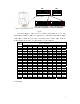
SW1 SW2 ON ON 1 2 3 4 5 6 7 8 9 10 1 DI P- - DI P9: Addr ess Sel ect 2 3 4 5 6 Pr ot ocol Sel ect ON ON 1 2 3 4 5 6 7 8 1 9 10 2 3 4 5 6 7 8 9 10 120Ω terminal resistor is 120Ω terminal resistor is connected on RS485 Bus opened for RS485 bus Figure 1 As shown in Figure 1, SW1 is used to set address of the P/T from 1 – 511. The ID-CODE from DIP-9 to DIP-1 are equivalent to a 9-bit binary digit. DIP-9 is MSB while DIP-1 is LSB.
ON ON 1 2 3 4 5 6 7 8 ON 1 9 10 P/ T Addr ess=1 ON 3 4 5 6 7 8 1 9 10 2 3 4 5 6 7 8 9 10 2 3 4 5 6 7 8 9 10 P/ T Addr ess=3 ON 1 ON 1 P/ T Addr ess=4 2、 2 P/ T Addr ess=2 2 3 4 5 6 7 8 9 10 1 P/ T Addr ess=5 2 3 4 5 6 7 8 9 10 P/ T Addr ess=511 Selection of the Terminal Resistor As shown in Figure 1, DIP10 of the ID-CODE is the select switch of the 120Ω terminal resistor on the bus RS485, on which only one terminal resistor of the dome camera at th
protocols are shown as follows: ON NEON/ 9600Bps ON 1 2 3 4 5 PANASONI C/ 9600Bps 6 ON PELCO- D/ 2400Bps 2 3 4 5 KALATEL/ 4800Bps 6 ON 4、 3 4 5 6 1 2 3 4 5 6 1 2 3 4 5 6 1 2 3 4 5 6 ON 1 2 3 4 5 ALEC/ 9600Bps 6 ON PELCO- P/ 9600Bps 2 ON 1 PELCO- P/ 4800Bps 1 ON 1 2 3 4 5 Ul t r ak/ 9600Bps 6 Setup of the Baud Rate of Communication.
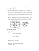
Figure 2 1. Connection P/T with controller : RS485 control signal 、power supply(AC24V)、video signal could connect with controller by air waterproof connector plug (D1). Figure 4 is Connect way of D1. Figure 3 is come out line of air connector plug. RED: AC24V I N BLACK: AC24V I N ORANGE: RS485+ YELLOW: RS485VI DEO: VI DEO OUT RED BLACK ORANGE YELLOW VI DEO Figure 3 2.
Figure 6 Ⅵ. Figure 7 INSTALLATION a、 This outdoor Pan/Tilt unit is intended to be mounted on a wall mount. The unit base has 4 holes equi-spaced on 4″ (101.6mm) P.C.D[see figure 8], which line up with the bracket mounting holes. Mount the unit base onto the bracket using the four M6×25 Hex head screws, 6mm washers and the M6 nuts provided in the packing kit. b、 Remove the six M4mm fixing screws from the top platform using the three M1/4″ -20screws (supplied).