
User guide


5
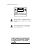
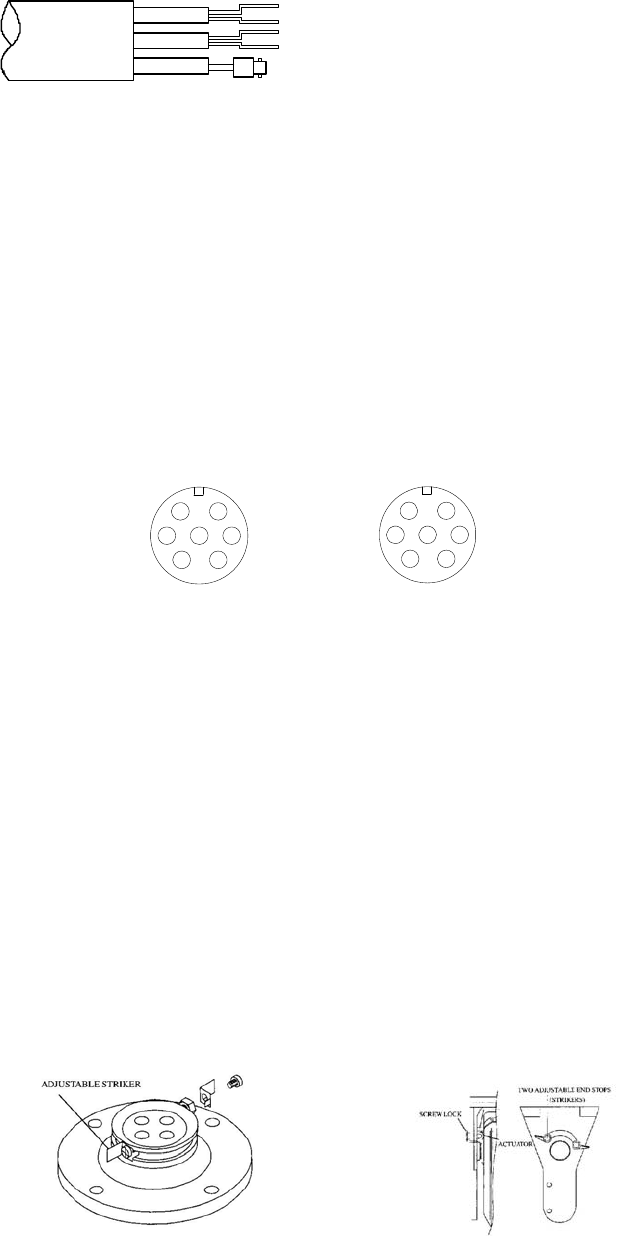
Figure 2
1. Connection P/T with controller : RS485 control signal 、power supply(AC24V)、video
signal could connect with controller by air waterproof connector plug (D1). Figure 4 is
Connect way of D1. Figure 3 is come out line of air connector plug.
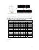
RE D
BL ACK
ORA NGE
YEL L OW
VI DEO
RE D: A C2 4 V I N
BL ACK: AC2 4 V I N
ORA NGE: RS4 8 5 +
YEL L OW: RS485-
VI DEO: VIDEO OUT
Figure 3
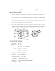
2. Connection of P/T and outdoor housing:when collocate the special decoder for housing,
decoder’s control signal input、Power supply(AC24V) and video signal output by air
waterproof connector plug (D2) to conncet . Figure 5 is connect way of D2. Note:Connect
P/T’s GND with lens decoder’s GND. Furthermore P/T’s TXD、RXD must cross connect
with lens decoder’s TXD、RXD,Otherwise,lens will not to be controlled. Otherwise,Could
not to preset lens’s position,only just could preset P/T’s postision.
1. AC24V I N
2. AC24V I N
3. RS485-
4. CABI NET GND
5. RS485+
6. VI DEO+
7. VI DEO-
1
2
34
5
6
7
D2
1 . AC2 4 V OUT
2 . AC2 4 V OUT
3. TXD( TTL LEVEL)
4. GND
5. RXD( TTL LEVEL)
6. VI DEO+
7. VI DEO-
1
2
3
4
5
6
7
D1
Figure 4 Figure 5
3. Control wiper:Use command(D-ZOOM ON)to startup wiper;Use command
(D-ZOOM OFF)to stop wiper. Also could use call NO.64 preset position to startup or
stop(switch controll) wiper.
Ⅴ . SETTING PAN/TILT END
a、 Setting the Pan limits (see figure 6)::Loosen the M4 screws and loosen the pan strikers. Adjust
the strikers until they are at the position to strike the relevant actuator, thus activating the
limit switches. Tighten the M4 screws to secure the pan strikers.
b、Setting the Tilt limits (see figure 7):Release the screw locks and adjust the strikers until they
are at the position to strike the actuator, thus activating the limit switches.