
User guide

Quick Setup with CME 2 Xenus XTL User Guide
108 Copley Controls Corp.
5.9: Current Loop
Initial current loop proportional gain (Cp) and current loop integral gain (Ci) values were calculated in
a previous step. For an introductory overview of the control loops, see
Operating Modes (p. 9).
NOTE: For Copley Controls digital amplifiers, the current loop gain is independent of the power supply
voltage.
5.9.1: Current Loop Settings
For more information, see Current Mode and Current Loop (p. 10).
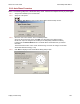
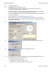
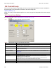
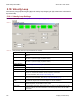
5.9.1.1 Click I Loop to open the Current Loop screen:
5.9.1.2 Change/verify Current Loop parameters as needed.
Parameter Description
Peak Current Limit Used to limit the peak phase current to the motor. Max value depends upon the amplifier
model; Min value > continuous limit.
I
2
T Time Limit Sets I
2
T Time Limit in mS. See I
2
T Time Limit Algorithm (p. 145).
Continuous Current Limit Used to limit the Phase Current. Max Value is < Peak Current and depends upon the
amplifier model. Min value: 0
Current Loop Offset Sets current loop offset. Leave it set to zero until after tuning. For more information, see
Offset (p. 10).
Cp Current loop proportional gain. Range 0 – 32,767.
Ci Current loop integral gain. Range 0 – 32,767.
Drive Output
Maximize Smoothness: Amplifier uses circular vector limiting to produce smooth
operation even into the voltage limits.
Maximize Speed: Allows for slightly more of the bus voltage to be used when in the
voltage limit. This may produce a small disturbance at top speed.
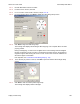
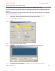
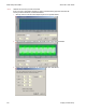
Auto Tune See Auto Tune the Current Loop (p. 109).
Bandwidth Measure bandwidth using the Cp and Ci values now in the amplifier.