
User guide

Quick Setup with CME 2 Xenus XTL User Guide
112 Copley Controls Corp.
5.10: Velocity Loop
Initial velocity loop proportional gain (Vp) and velocity loop integral gain (Vi) values were calculated in
a previous step.
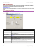
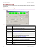
5.10.1: Velocity Loop Settings
For more information, see Velocity Mode and Velocity Loop (p. 12).
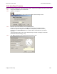
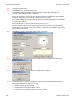
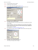
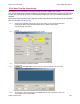
5.10.1.1 Click V Loop.
5.10.1.2 Change/verify Velocity Loop parameters as needed.
Parameter Description
Velocity Limit Top speed limit. Max value may depend upon the back EMF & the Encoder value. Min
value: 0.
Acceleration Limit Maximum acceleration rate. Max value may depend upon load, inertia, & peak current.
Min value: 1. (Does not apply in position mode.)
Deceleration Limit Maximum deceleration rate. Max value may depend upon load, inertia, & peak current.
Min value: 1. (Does not apply in position mode.)
Tracking Window
Tracking Time
See Tracking Window Details (p. 30).
Vp Velocity loop proportional gain. Range: 0 to 32,767.
Vi Velocity loop integral gain. Range: 0 to 32,767.
Fast Stop Ramp Deceleration rate used by the velocity loop when the amplifier is hardware disabled.
Range: 0 to 100,000,000. Default: velocity loop Decel. Limit value.
For more information, see Velocity Loop Limits (p. 12).
Enable Gains Scalar Increases the resolution of the units used to express Vp and Vi, providing more precise
tuning. For more information, see Velocity Loop Gains Scalar (p. 13).
Vi Drain (integral
bleed)
Vi drain modifies the effect of velocity loop integral gain. The higher the Vi Drain value,
the faster the integral sum is lowered. Range: 0 to 32,000. Default: 0.
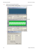
Command Filter Programmable command input filter. Disabled by default. For more information on the
velocity loop filters, see the CME 2 User’s Guide.
Output Filter Programmable output filter. Default filter type: Low-Pass, 2-pole Butterworth (Cut Off
Frequency 200 Hz). For more information on the velocity loop filters, see the CME 2
User Guide.