
User guide


Operational Theory Xenus XTL User Guide
12 Copley Controls Corp.
2.5.3: Velocity Mode and Velocity Loop
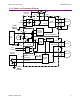
Velocity Loop Diagram
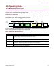
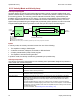
As shown below, the velocity loop limiting stage accepts a velocity command, applies limits, and
passes a limited velocity command to the input filter. The filter then passes a velocity command to
the summing junction. The summing junction subtracts the actual velocity, represented by the
feedback signal, and produces an error signal. (The velocity loop feedback signal is always from
the motor feedback device even when an additional encoder is attached to the load.) The error
signal is then processed using the integral and proportional gains to produce a current command.
Programmable digital filters are provided on both the input and output command signals.
Velocity
C
ommand
Current
Command
Velocity Limiter
Velocity Loop
Feedback (Derived Velocity)
Limits :
Velocity
Acceleration*
Deceleration*
E
mergency Stop Deceleration*
*Not used w hen velocity loop is controlled by position loop. See "Velocity Loop Limits" for details.
Velocity Integral Gain (Vi)
V
elocity Proportional Gain (Vp)
Limited
Velocity
+
-
+
+
Filter
Filte r
Inputs
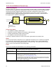
In velocity mode, the velocity command comes from one of the following:
• The amplifier’s analog or PWM inputs.
• A network command, CANopen, DeviceNet, or RS-232 Serial.
• A Copley Virtual Motion (CVM) control program.
• The amplifier’s internal function generator.
In position mode, the velocity command is generated by the position loop.
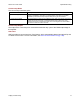
Velocity Loop Limits
The velocity command is limited based on the following set of parameters designed to protect the
motor and/or the mechanical system.
Limiter Description
Velocity Limit Sets the maximum velocity command input to the velocity loop.
Acceleration Limit Limits the maximum acceleration rate of the commanded velocity input to the velocity loop.
This limit is used in velocity mode only.
Deceleration Limit Limits the maximum deceleration rate of the commanded velocity input to the velocity loop.
This limit is used in velocity mode only.
Fast Stop Ramp Specifies the deceleration rate used by the velocity loop when the amplifier is hardware
disabled. (Fast stop ramp is not used when amplifier is software disabled.) If the brake
delay option is programmed, the fast stop ramp is used to decelerate the motor before
applying the brake.
Note that Fast Stop Ramp is used only in velocity mode. In position mode, the trajectory
generator handles controlled stopping of the motor. There is one exception: if a non-latched
following error occurs in position mode, then the amplifier drops into velocity mode and the
Fast Stop Ramp is used.
For more information, see Following Error Fault Details (p. 29).