
User guide

Xenus XTL User Guide Operational Theory
Copley Controls Corp. 23
2.8: Brake Operation
2.8.1: Digital Output Controls Brake
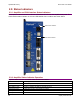
Many control systems employ a brake to hold the axis when the amplifier is disabled. Digital output
4 (OUT4) is designed specifically for a brake output. (Other outputs can be used for brake control,
but OUT4 is recommended.) Unlike the other outputs, OUT4 is optically isolated from the control
signals and has an internal fly back diode connected to the +24 Vdc input. By eliminating the need
to connect into the amplifier control connector, having the brake output on the +24 Vdc power
connector simplifies wiring when the brake wires are in the power cable of the motor.
For more information, see Brake Output (p. 39) and Logic Supply / Brake (J4) (p. 52).
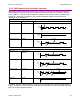
2.8.2: Brake/Stop Sequences
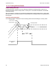
Disabling the amplifier by a hardware or software command starts the following sequence of
events.
• The motor begins to decelerate (at Abort Deceleration rate in position mode or Fast Stop
Ramp rate in velocity mode). At the same time, the Brake/Stop Delay Time count begins. This
allows the amplifier to slow the motor before applying the brake.
• When the motor slows to Brake/Stop Activation Velocity OR the Brake/Stop Delay Time
expires, the brake output activates and PWM Delay Brake/Stop Response Time count begins.
• When response time has passed, the amplifier’s output stages are disabled. This delay
ensures the brake has time to lock in before disabling the power section.
This sequence is not available in the current mode of operation. Instead, in current mode, the
amplifier output turns off and the brake output activates immediately when the disable command is
received.