
User guide

Operational Theory Xenus XTL User Guide
32 Copley Controls Corp.
2.13: Inputs
2.13.1: Digital Inputs
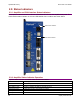
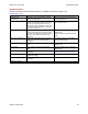
The amplifier has twelve digital inputs (IN1-IN12). Eleven of them appear on the control connector.
IN5 appears on the feedback connector, and is intended for the motor over temperature switch
(although it can be programmed for any function). For a list of input functions, see Digital Input
Functions (p. 86 ).
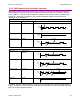
2.13.2: Input Filters
Two types of input RC filters are used: GP (general-purpose) and HS (high-speed). Input
reference functions such as Pulse and Direction, Pulse Up/Pulse Down, and Quadrature A/B are
wired to inputs that have the HS filters, and inputs with the GP filters are used for general-purpose
logic functions, limit switches, and the motor temperature sensor.
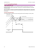
2.13.3: Debounce Time
To prevent undesired multiple triggering caused by switch bounce upon switch closures, each
input can be programmed with a debounce time. The programmed time specifies how long an
input must remain stable at a new state before the amplifier recognizes the state. The debounce
time is ignored if the input is used as a digital command input.
2.13.4: Configure for Pull Up/Pull Down Resistors by Groups
Pre-defined groups of inputs can be programmed to have either an internal pull up or pull down
resistor. See J7 Pin Description (p. 56)
for groupings.