
User guide

Specifications Xenus XTL User Guide
38 Copley Controls Corp.
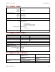
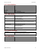
3.7: Analog Command Input
Channels 1
Type Differential, non-isolated
Measurement Range ±10 Vdc
Maximum Voltage
Differential
Input to Ground
±10 Vdc
±10 Vdc
Input Impedance
66 k
Resolution 12 Bit
Bandwidth 7 kHz
Scan Time
67 µSec
Function Current, velocity, or position command
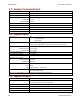
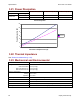
3.8: Digital Inputs
Channels 12*
7 general-purpose
5 high-speed
Type 74HC14 Schmitt trigger w/ RC filter
10 k resistor programmable as pull up or pull down to internal +5 Vdc.
Input Voltage Range
General-Purpose
High-speed
0 V - +28 Vdc
0 V - +12 Vdc
Logic Low Input Voltage < +1.35 Vdc
Logic High Input Voltage > +3.65 Vdc
Scan Time
333 µSec
RC Filter Time Constant
General-Purpose
High-speed
330 µSec
100 nSec
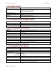
Debounce
Type
Time
Digital
Programmable 0 - 10,000 mSec
Function IN1 enable
IN2 - IN12 programmable
Note: Inputs 7&9 and 8&10 can be programmed to function as differential pairs.
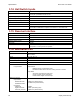
3.9: Digital Outputs
Channels 3
Type Current-sinking MOSFET, non-isolated
1 k pullup to internal +5 Vdc through diode
Maximum Voltage +40 Vdc
Maximum Sink Current 1 A
Low Level Output Resistance
<0.2
Function Programmable