
User guide

Xenus XTL User Guide Specifications
Copley Controls Corp. 41
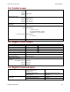
3.17: Serial Interface
Channels 1
Type RS-232
Signals Rxd, Txd, Gnd
Baud Rate 9,600 to 115,200 (defaults to 9600 on power up or reset)
Data Format N, 8, 1
Flow Control None
Protocol Binary or ASCII format
Function Set up, control and diagnostics status
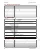
3.18: CAN Interface
Channels 1
Connectors 2 eight-position modular (RJ-45 style) wired as per CAN Cia DR-303-1, V1.1
One connector for signal input.
Second connector for daisy chaining to next node.
Signals CAN H, CAN L, CAN Gnd
(CAN +5 Vdc Pass though only)
Format CAN V2.0b physical layer for high-speed connections compliant
Protocol Motion Control Device
Under DSP-402 of the CANopen DS-301 V4.01 (EN 50325-4) Application
Layer
Supported Modes Profile Current, Velocity, and Position, PVT, and Homing
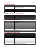
Node Address Selection 16-position rotary switch on front panel
OR programmable digital inputs
OR stored in flash memory
OR combination of above.
Bus Termination
External 121 resistor across CAN-H and CAN-L when termination plug is
installed in second connector.
Function Real-time motion control
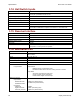
3.19: Status Indicators
Amplifier Status Bi-Color LED on front panel, labeled Status*.
CAN Status Bi-Color LED on front panel, labeled CAN.
Conforms to CAN Indicator Specification CiA DR-303-3*.
*For status indicator locations and codes, see Status Indicators (p. 24).
3.20: Fault Levels
Amp Over Temperature > 80 °C
DC Bus Under Voltage < +60 Vdc
DC Bus Over Voltage > +400 Vdc
Encoder Power < +4.25 Vdc