
User guide


Xenus XTL User Guide Wiring
Copley Controls Corp. 47
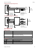
J2 and J3 Grounds
The ground terminals at J2-1 and J3-5 also connect to the amplifier chassis.
Motor cases can be safety-grounded in one or optionally both of these ways:
• Direct grounding of the motor frame (assuming the frame of the machine is grounded). Attach
the metal motor case to the metal machine frame or connect the ground wire of the motor to
the metal frame of the machine.
• Grounding of the motor frame through the motor power cable to amplifier J2-1. The ground
wire should be of the same gauge as the power wires.
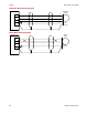
Likewise, the case of the regen resistor can also be safety-grounded by direct grounding of the
case or by a grounding wire connected to amplifier J3-5. Again, this wire should be of the same
gauge as the other regen resistor conductors.
Cable shields, because of their smaller wire size, must not be used as part of a safety-ground
system.
Signal Grounding
The amplifier signal ground must be connected to the control system signal ground. The amplifier
signal ground is not connected to earth ground internal to the amplifier. Therefore, the control
system signal ground can be connected to earth ground without introducing a ground loop.
Shielding
Shields on cables reduce emissions from the amplifier and help protect internal circuits from
interference due to external sources of electrical noise. The shields shown in the wiring diagrams
are also required for CE compliance. Cable shields should be tied at both ends to earth or chassis
ground. The housing and pin 1 of both J7 and J8 are connected to the amplifier’s chassis.
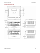
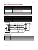
4.1.3: Connector Locations
Connector locations (J1-J8) are shown below.