
User guide

Xenus XTL User Guide Wiring
Copley Controls Corp. 57
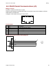
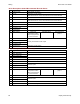
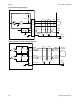
Mode-Dependant Dedicated Inputs
T
hese inputs are dedicated to specific functions, depending on operating mode.
Selected Command Source
Mode
Digital Input
Single Ended
Digital Input
Differential
Multi-Mode
Port
Function
Current & Velocity
PWM 50%
9 9(+) & 7(-) A & /A PWM Input
9 9(+) & 7(-) A & /A PWM Input Current & Velocity
PWM 100%
10 10(+) & 8(-) B & /B Direction Input
9 9(+) & 7(-) A & /A Pulse Input Position
Pulse & Direction
10 10(+) & 8(-) B & /B Direction Input
9 9(+) & 7(-) A & /A Count Up Position
Up/Down
10 10(+) & 8(-) B & /B Count Down
9 9(+) & 7(-) A & /A Channel A Position
Quadrature
10 10(+) & 8(-) B & /B Channel B
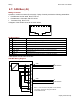
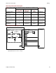
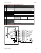
Digital Inputs Wiring Diagram
Amplifier
J7-10
J7-11
J7-12
J7-13
J7-14
J7-15
J7-4
J7-5
J7-6
J7-7
J7-8
J7-9
IN4
IN3
IN2
IN1 (Enable)
IN11
IN12
IN6
IN7
IN8
IN9
IN10
Signal
Ground
J7
Motion
Controller
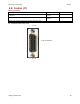
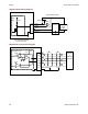
* Standard input R = 10 K
C = 0.033
µ
ƒ
High-speed input R = 1K
C = 100 pƒ
R*
10 K
pull up / pull dow n
+ 5Vdc
74HC14
C*
Typical
Circuit