
User guide

Wiring Xenus XTL User Guide
60 Copley Controls Corp.
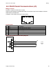
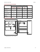
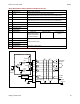
J8 Pin Description Quad A/B Incremental Encoder Xenus
Pin Signal Function
1 Frame Ground Cable shield connection
2 +5 Vdc Signal and +5 Vdc ground.
Total load current on J7-20, J8-2, and J8-4 not to exceed 400 mA.
3 Digital Hall U
4 +5 Vdc Encoder and/or Halls +5 Vdc power supply output.
Total load current on J7-20, J8-2, and J8-4 not to exceed 400 mA.
5 Signal Ground Signal and +5 Vdc ground
6 Digital Hall V
7 Encoder /X Input
8 Encoder X Input
Primary incremental encoder inputs
9 Digital Hall W
10 [IN5] Motemp Motor over
temperature switch
May be programmed
to other functions
Standard speed Pull-up/pull-down
group 2
11 Encoder /B Input
12 Encoder B Input
13 Encoder /A Input
14 Encoder A Input
Primary incremental encoder inputs
15 Signal Ground Signal and +5 Vdc ground
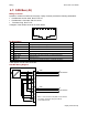
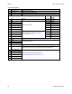
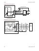
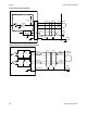
J8 Pin Description Resolver Xenus (-R)
Pin Signal Function
1 Frame Ground Cable shield connection
2 Ref(-) Output R2
3 Ref(+) Output R1
Resolver excitation
4 N.C.
5 Signal Ground Signal and +5 Vdc ground
6 Frame Ground Cable shield connection
7 Sin(-) Input S1
8 Sin(+) Input S3
Resolver inputs
9 N.C.
10 [IN5] Motemp Motor over
temperature switch
May be programmed
to other functions
Standard speed Pull-up/pull-down
group 2
11 Frame Ground Cable shield connection
12 Cos(-) Input S4
13 Cos(+) Input S2
Resolver inputs
14 N.C.
15 Signal Ground Signal and +5 Vdc ground