
User guide

Quick Setup with CME 2 Xenus XTL User Guide
74 Copley Controls Corp.
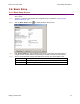
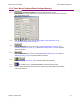
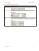
5.4.1.6 View or change the Feedback settings described below. Options vary with amplifier model.
Setting Description
Hall Type Select Hall type: None, Digital, or Analog (Analog is used with Copley
Controls ServoTube motors).
Hall Phase
Correction
If selected, will enable error checking between Hall switches and encoder
based phase angle.
Motor Encoder Select type and source of motor feedback.
• None: No motor encoder.
• Primary Incremental: Incremental encoder on primary feedback connector.
• Secondary Incremental: Incremental encoder on multi-mode port.
• Analog: Analog encoder on primary feedback connector.
• Low Frequency Analog: Copley ServoTube motor on primary feedback
connector.
• Resolver (Resolver version only): Resolver on primary feedback connector.
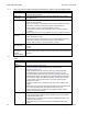
Position
Encoder
Select type and source of Position (load) feedback.
• None: No position encoder.
• Primary Incremental: Incremental encoder on primary feedback connector.
• Secondary Incremental: Incremental encoder on multi-mode port.
• Analog: Analog encoder on primary feedback connector.
Position
Encoder Type
Select the type of Position (load) encoder:
• Rotary.
• Linear.
Use Position
Encoder in
Passive
(Monitor) Mode
When this is checked, the position of the position encoder will be reported by
the passive load position variable but it will not be used to control the position
of the axis.
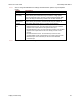
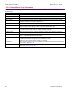
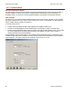
5.4.1.7 View or change the Operating Mode settings described below. Options vary with amplifier
model.
Setting Description
Operating
Mode
Choose the mode of operation: Current, Velocity, or Position.
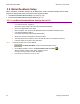
Command
Source
Choose the command input source:
• Analog Command: Analog voltage provides command input.
See Analog Input (p. 96).
• PWM command (current and velocity mode only): Digital pulse-width
modulated signal provides command input. See PWM Input (p. 98).
• Function Generator: Internal function generator provides command input.
• Software Programmed: The amplifier is controlled by software commands
from either the Copley Virtual Machine (CVM) or an external source. See
Copley Indexer Program User’s Guide or the Copley ASCII Interface
Programmer’s Guide.
• Camming: Amplifier runs in Camming Mode. See Copley Camming User
Guide.
• Digital Input: Command input is provided via the Input Source selected from
the choices described below. See Digital Position Input (p. 99).
• CAN: Command input is provided over the CANopen network. See the
CANopen Programmer’s Guide.
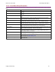
Input Source Choose the input source for PWM or Digital input commands:
• Single-ended Inputs: Command input is provided via two of the amplifier’s
programmable digital inputs.
• Multi-mode Port: Command input is provided via differential inputs on the
amplifier’s multi-mode port.
• Differential Inputs: Command is provided via the amplifier’s differential
inputs.