
User guide

Xenus Plus User Guide Wiring
Copley Controls 111
…Pin Description, continued:
21
OUT3+ GPI
Optically isolated programmable output positive signal.
22
OUT4+ GPI
23
OUT5+ GPI
24
N/C
No connection.
25
N/C
26
N/C
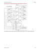
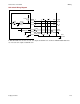
800-1782 Pin Description
Pin
Signal
Function
1
Frame Ground
Cable shield connection.
2
IN6 GPI
Optically isolated programmable input.
3
IN7 GPI
4
IN8 GPI
5
IN9 GPI
6
COM1
Common signal for first group of optically isolated programmable inputs (IN6-IN9)
7
IN16 GPI
Optically isolated programmable input.
8
IN17 GPI
9
IN18 GPI
10
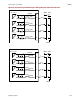
OUT1- GPI
Optically isolated programmable output negative signal.
11
OUT2- GPI
12
OUT3- GPI
13
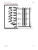
S1_A
S1_A~S4_A signals are outputs driven by 453 ohm resistors that connect to an
internal voltage source +6VISO. These provide limited current to drive the input diode
anodes of optical limit switches on the motor.
14
S2_A
15
S3_A
16
S4_A
17
N/C
No connection
18
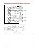
IN19 GPI
Optically isolated programmable input.
19
OUT1+ GPI
Optically isolated programmable output positive signal.
20
OUT2+ GPI
21
OUT3+ GPI
22
S1_RTN
S1_RTN~S4_RTN connect to the input diode cathodes of the optical limit switches on
the motor.
23
S2_RTN
24
S3_RTN
25
S4_RTN
26
N/C
No connection.