
User guide

Xenus Plus User Guide Wiring
Copley Controls 116
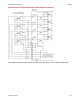
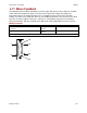
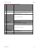
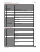
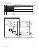
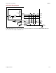
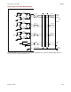
Pin Description Quad A/B Incremental Encoder
Pin
Signal
Function
1
Frame Ground
Cable shield connection.
2
Digital Hall U
3
Digital Hall V
4
Digital Hall W
5
Signal Ground
Signal and +5 Vdc ground.
6
+5 Vdc
Encoder and/or Halls +5 Vdc power supply output.
Total load current on J10-6, J10-17, and J8-20 not to exceed 400 mA.
7
Motemp
Motor over temperature switch. May be programmed to other functions.
Analog input on the XEL/XPL/XML models. Digital input on the
XE2/XP2/800-1808 models.
8
Encoder /X1 Input
Primary incremental encoder inputs.
9
Encoder X1 Input
10
Encoder /B1 Input
11
Encoder B1 Input
12
Encoder /A1 Input
13
Encoder A1 Input
14
Encoder /S1 Input
15
Encoder S1 Input
16
Signal Ground
Signal and +5 Vdc ground.
17
+5 Vdc
Encoder and/or Halls +5 Vdc power supply output.
Total load current on J10-6, J10-17, and J8-20 not to exceed 400 mA.
18
Sin1(-)
Analog Sin/Cos/Index encoder signals.
19
Sin1(+)
20
Cos1(-)
21
Cos1(+)
22
Index1(-)
23
Index1(+)
24
IN15 (XEL/XPL/XML)
IN21/IN22 (XE2/XP2)
General purpose input
(IN21 is on J10, IN22 is on J11)
25
Signal Ground
Signal and +5 Vdc ground.
26
Signal Ground
Signal and +5 Vdc ground.