
User guide

Xenus Plus User Guide Wiring
Copley Controls 118
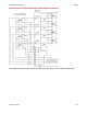
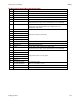
…Pin Description, continued:
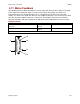
17
+5 Vdc
Encoder +5 Vdc power supply output.
Total load current on J10-6, J10-17, and J8-20 not to exceed 400 mA.
18
Resolver Inc A
Type 2 & Type 1 motors
19
Resolver Inc B
20
Resolver Inc C
21
N/C
No connection
22
N/C
23
Resolver Ref(+)
Resolver Ref inputs.
24
N/C
No connection
25
Signal ground
Signal and +5 Vdc ground.
26
Signal ground
Signal and +5 Vdc ground.
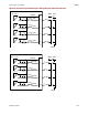
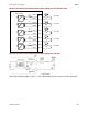
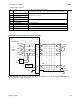
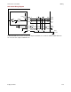
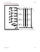
Quad A/B Incremental Encoder Wiring Diagram
In XEL/XPL/XML there are two encoder +5V outputs at 400 mA each, and in the XE2/XP2/800-1808 there
are 4 encoder +5V outputs at 500 mA each.
Drive
J1
0
J1
0
-
13
J1
0
-
12
J1
0
-
10
J1
0
-
9
J1
0
-
11
J1
0
-
8
+
5
VDC
A
B
Inde
x
Incremental
Encoder
Encoder
Power
Case
Ground
Typical Circuit
T
o
Encode
r
Output
121
A
B
X
Index
B
A
A
B
X
Gnd
+
-
+
-
+
-
121
121
MAX 3097
MAX 3097
MAX 3097
MAX 3362
Frame
Gnd
J1
0
-
1
J1
0
-
6
J1
0
-
5
5V
@ 400
m
A