
User guide

Xenus Plus User Guide Operational Theory
Copley Controls 33
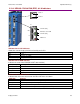
2.7.2: EtherCAT Communication Details (XEL/XE2/800-1782)
The XEL/XE2/800-1782 models accept CAN application layer over EtherCAT (CoE) commands.
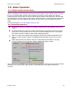
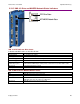
EtherCAT Addressing
Nodes on an EtherCAT network are automatically addressed by their location. The first drive on
the network is station address -1. The second is -2, and so on. Each dual axis drive is addressed
as a single physical node on the EtherCAT network having two axes of motion.
As an alternate to the default addressing, switches S1 and S2 may be used to program a drive’s
Device ID with a value between 0x01 and 0xFF (1-255 decimal). In dual axis drives the second
drive follows the first’s Device ID value.
The default address and station alias are always available. If the switch-based station alias is
used, it is the responsibility of the user to ensure that each drive has a unique station alias.
2.7.3: MACRO Communication Details (XML/800-1808)
The XML/800-1808 typically runs in torque mode accepting commands over the MACRO network.
(Velocity mode is also supported.)
MACRO Addressing
A MACRO network, or ring for the XML/800-1808 can have up to sixteen master controllers with
hex addresses from 0x00 to 0x0F. Each master can control up to eight servo drives. This works
out to a maximum of 128 servo drives on a MACRO ring.
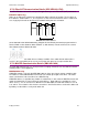
A MACRO address is eight bits long. Switch S1 controls bits 7~4 to select the MACRO master and
switch S2 controls bits 3~0 and selects the node address. Node addresses available for servo
drives are: 0~1, 4~5, 8~9, and 12~13. With the 2-axis 800-1808, the valid node addresses are: 0,
4, 8, and 12. These address Axis A of the servo drives. Axis B of the drives can then be addressed
by adding 1 to the address set by node switch S2.
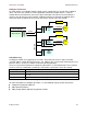
XEL
J7
XEL
J7
XEL
Control
J7
-1 -2 -3
Default EtherCAT station addresses