
User guide

Xenus Plus User Guide Operational Theory
Copley Controls 45
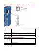
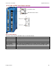
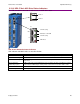
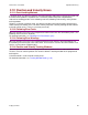
2.10.9: XP2 J7 Axis A/B: Drive Status Indicators
The LEDs located on connector J7 indicate axis A and B drive status.
XP2 J7 Axis A/B: Drive Status Indicators
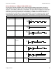
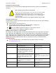
XP2 indicator color/blink codes are described below.
Color/Blink Code
Meaning
Green/Solid
Drive OK and enabled. Will run in response to reference inputs or CANopen commands.
Green/Slow Blinking
Drive OK but NOT-enabled. Will run when enabled.
Green/Fast Blinking
Positive or Negative limit switch active. Drive will only move in direction not inhibited by
limit switch.
Green flash twice
followed by a pause
STO is active, One or both STO inputs are de-energized. The drive is hardware & software
enabled but the PWM outputs cannot produce current in the motor when STO is active.
Red/Solid
Transient fault condition. Drive will resume operation when fault is removed.
Red/Blinking
Latching fault. Operation will not resume until fault is cleared or drive is Reset.
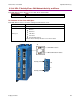
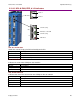
Out
In
J7
J8
RUN-State of the ESM
L/A-Link activity
ERR-Errors
L/A-Link activity
A-Axis A
B-Axis B