
User guide

Xenus Plus User Guide Operational Theory
Copley Controls 48
Clearing Non-Latched Faults
The drive clears a non-latched fault, without operator intervention, when the fault condition is
corrected.
DANGER
Risk of unexpected motion with non-latched faults.
After the cause of a non-latched fault is corrected, the drive re-enables the PWM
output stage without operator intervention. In this case, motion may re-start
unexpectedly. Configure faults as latched unless a specific situation calls for non-
latched behavior. When using non-latched faults, be sure to safeguard against
unexpected motion.
Failure to heed this warning can cause equipment damage, injury, or death.
Clearing Latched Faults
A latched fault is cleared only after the fault has been corrected and at least one of the following
actions has been taken:
power-cycle the +24 Vdc to the drive
cycle (disable and then enable) an enable input that is configured as
Enables with Clear Faults or Enables with Reset
access the CME 2 Control Panel and press Clear Faults or Reset
clear the fault over the CANopen network or serial bus
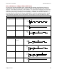
Example: Non-Latched vs. Latched Faults
For example, the drive temperature reaches the fault temperature level and the drive reports the
fault and disables the PWM output. Then, the drive temperature is brought back into operating
range. If the Drive Over Temperature fault is not latched, the fault is automatically cleared and the
drive’s PWM outputs are enabled. If the fault is latched, the fault remains active and the drive’s
PWM outputs remain disabled until the faults are specifically cleared (as described above).
Fault Descriptions
The set of possible faults is described below. For details on limits and ranges,
see Fault Levels (p. 73)
Fault Description
Fault Occurs When…
Fault is Corrected When…
*Drive Over Temperature
Drive’s internal temperature exceeds
specified temperature.
Power module temperature falls below
specified temperature.
Motor Phasing Error
Encoder-based phase angle does not
agree with Hall switch states. This fault can
occur only with brushless motors set up
using sinusoidal commutation. It does not
occur with resolver feedback or with Halls
correction turned off.
Encoder-based phase angle agrees
with Hall switch states.
*Feedback error
Over current condition detected on the
output of the internal +5 Vdc supply used to
power the feedback. Resolver or analog
encoder not connected or levels out of
tolerance.
Encoder power returns to specified
voltage range.
Feedback signals stay within specified
levels.
*Motor Over Temperature
Motor over-temperature switch changes
state to indicate an over-temperature
condition.
Temperature switch changes back to
normal operating state.
Under Voltage
Bus voltage falls below specified voltage
limit.
+ DC bus voltage returns to specified
voltage range.
Over Voltage
Bus voltage exceeds specified voltage limit.
+ DC bus voltage returns to specified
voltage range.
!