
User guide

Xenus Plus User Guide Operational Theory
Copley Controls 53
2.13: Inputs XEL/XPL/XML
The Xenus Plus XEL and XPL drives have 15 digital inputs and 3 analog inputs.
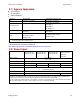
2.13.1: Digital Inputs
The Xenus Plus XEL and XPL drives feature 14 programmable digital inputs. Non-isolated inputs
IN1-IN6 are connected on J8. Opto-isolated IN7-IN14 are connected on J9. IN3-IN6 are single
ended or differential programmable inputs.
The IN15 digital input on J10 is for an encoder fault signal on. For a list of input functions, see the
CME 2 User Guide.
Input Filters
Two types of input RC filters are used: GP (general-purpose) and HS (high-speed). Input reference
functions such as Pulse and Direction, Pulse Up/Pulse Down, and Quadrature A/B are wired to
inputs that have the HS filters, and inputs with the GP filters are used for general-purpose logic
functions, limit switches, and the motor temperature sensor.
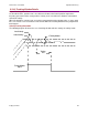
Debounce Time
To prevent undesired multiple triggering caused by switch bounce upon switch closures, each
input can be programmed with a debounce time. The programmed time specifies how long an
input must remain stable at a new state before the drive recognizes the state. The debounce time
is ignored if the input is used as a digital command input.
Configure for Pull Up/Pull Down Resistors by Groups
Pre-defined groups of inputs can be programmed to have either an internal pull up or pull down
resistor. See J8 Pin Description (p. 99) for groupings.
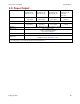
2.13.2: Analog Inputs
Two programmable differential analog inputs, AIN1 and AIN2, are connected on J8 with ±10 Vdc
range. As a reference input [AIN1] can take position/velocity/torque commands from a controller.
The second input [AIN2] is programmable for other functions. The ratio of drive output current or
velocity vs. reference input voltage is programmable.
Analog input [AIN3] Motemp is for use with a motor over temperature switch or sensor connected
on J10.