
User guide

Xenus Plus User Guide Operational Theory
Copley Controls 55
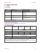
2.15: Outputs, XEL/XPL/XML
The Xenus Plus XEL and XPL drives have 6 programmable digital outputs (one opto-isolated and
five non-isolated) and one programmable analog output.
2.15.1: Digital Outputs
The XEL/XPL/XML features six programmable digital outputs. OUT1~5 are general-purpose
outputs. OUT6 is specifically designed as a brake output but can be programmed to perform any of
the functions. For a list of digital output functions, see Control I/O (p. 99)
OUT1~OUT3 are connected on J8. Opto-isolated OUT4 and OUT5 are on J9. OUT6 (Brake) is on
J4.
OUT1 and OUT2 are current sinking MOSFETs, each with a pull-up resistor, in series with a diode,
connected to the drive’s internal +5 Vdc supply. This design allows the outputs to be directly
connected to optically isolated PLC inputs that reference a voltage higher than +5 Vdc, typically
+24 Vdc. The diode prevents current flow between the +24 Vdc supply and the internal +5 Vdc
supply though the pull-up resistor. This current, if allowed to flow, could turn on the PLC input,
giving a false indication of the drive’s true output state. OUT1 and OUT2 require an external fly-
back diode to be installed across any inductive loads, such as relays, that are connected to them.
OUT3 is a 5V high speed buffered CMOS output.
OUT4 and OUT5 are opto-isolated with a 30 Vdc maximum output. Zener clamping diodes across
outputs allow driving of resistive-inductive (R-L) loads without external flyback diodes. They can
sink up to 1A from a motor brake connected to the +24 supply.
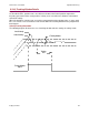
The brake output (OUT6) is described in Brake Operation (p. 35).
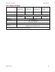
2.15.2: Analog Output
There is one programmable analog output (AOUT1). It has an output voltage range of ±5 Vdc. An
op-amp buffers the output of a 12-bit D/A converter.