
User guide

Xenus Plus User Guide Wiring
Copley Controls 97
4.8.2: CAN Bus (XPL/XP2)
Mating Connector
8-position, modular connector (RJ-45 style). Copley Controls provides the following assemblies:
Prefabricated 10 foot cable, PN XPL-NC-10
Prefabricated 1 foot cable, PN XPL-NC-01
Terminator Plug, PN XPL-NT
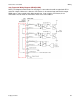
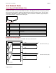
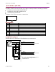
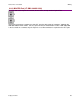
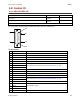
A diagram of the female connector is shown below.
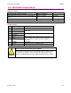
Pin Description*
Pin
Signal
Function
1
CAN_H
CAN_H bus line (dominant high)
2
CAN_L
CAN_L bus line (dominant low)
3
CAN_Gnd
Ground / 0 V / V-
4
--
No connection
5
--
Pass through to second connector, no internal connection
6
CAN_SHLD
Pass through to second connector, no internal connection
7
CAN_Gnd
Ground / 0 V / V-
8
CAN V+
Pass through to second connector, no internal connection
*Table applies to both CAN connectors
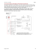
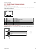
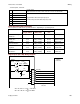
CAN Bus Wiring Diagram
The XPL drive uses connector J7. The XP2 drive uses connector J8.
1 2 3 4 5 6 7 8
Drive Jx
CAN +
CAN
-
CAN Gnd
CAN +
CAN
-
CAN Gnd
Note 1: If this is the last amplifier on the network,
use Copley Terminator Plug PN XPL-NT
to terminate the bus.
CAN Network
CAN Network
Jx-1
Jx-2
Jx-4
Jx-3
Jx-5
Jx-6
Jx-7
Jx-8
Jx-1
Jx-2
Jx-4
Jx-3
Jx-5
Jx-6
Jx-7
Jx-8
Opto-isolation