
User guide

Control Loops CME 2 User Guide
118 Copley Controls
11.3: Notes on the Current Mode and Current Loop
11.3.1: Current Loop Diagram
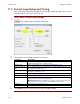
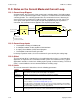
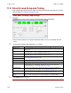
As shown below, the “front end” of the current loop is a limiting stage. The limiting stage
accepts a current command, applies limits, and passes a limited current command to the
summing junction. The summing junction takes the commanded current, subtracts the
actual current (represented by the feedback signal), and produces an error signal. This
error signal is then processed using the integral and proportional gains to produce a
command. This command is then applied to the amplifier’s power stage.
Current Command
PWM
Command
Current Limiter
Current Loop
Feedback (Actual Current)
Limits:
Peak Current
Continuous Current
Peak Current Limit Time
Current Integral Gain (Ci)
Current Proportional Gain (Cp)
Limited Current
+
-
+
+
Motor
Current Offset
11.3.2: Current Loop Inputs
The amplifier’s analog or PWM inputs.
A CANopen network via the amplifier’s CAN interface.
A Copley Virtual Motion (CVM) control program.
The amplifier’s internal function generator.
In velocity or position modes, the current command is generated by the velocity loop.
11.3.3: Offset
The current loop offset is intended for use in applications where there is a constant force
applied to, or required of, the servomotor and the system must control this force. Typical
applications would be a vertical axis holding against gravity, or web tensioning. This offset
value is summed with the current command before the limiting stage.
11.3.4: Limits
The current command is limited based on the following parameters:
Limiter
Description
Peak Current
Limit
Maximum current that can be generated by the amplifier for a short duration of time. This
value cannot exceed the peak current rating of the amplifier.
Continuous
Current Limit
Maximum current that can be constantly generated by the amplifier.
I
2
T Time Limit
Maximum amount of time that the peak current can be applied to the motor before it must
be reduced to the continuous limit or generate a fault.
For more details, see I2T Time Limit Algorithm (p. 191).
Note: Although the current limits set by the user may exceed the amplifier's internal limits,
the amplifier operates using both sets of limits in parallel, and therefore will not exceed its
own internal limits regardless of the values programmed.
Ramp
Rate of change in current command. Used to limit jog moves initiated from the Control
Panel Jog function in current mode, and in advanced Indexer Program functions.