
User guide

Control Loops CME 2 User Guide
120 Copley Controls
11.4: Velocity Loop Setup and Tuning
Initial velocity loop proportional gain (Vp) and velocity loop integral gain (Vi) values can be
calculated with The Calculate Function (p. 54).
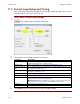
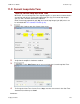
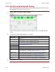
Enter basic Velocity Loop settings
1
Click V Loop (screen contents vary with model and configuration):
Note: For Plus products the output and command filter are accessed through the filter
screen.
2
Change/verify Velocity Loop parameters as needed.
Parameter
Description
Velocity Limit
Top speed limit. Max value may depend upon the back EMF & the Encoder value.
Min value: 0.
Acceleration Limit
Maximum acceleration rate. Max value may depend upon load, inertia, & peak
current. Min value: 1. (Does not apply in position mode.)
Deceleration Limit
Maximum deceleration rate. Max value may depend upon load, inertia, & peak
current. Min value: 1. (Does not apply in position mode.)
Tracking Window
See Tracking Window Details (p. 92).
Tracking Time
Vp
Velocity loop proportional gain. Range: 0 to 32,767.
Vi
Velocity loop integral gain. Range: 0 to 32,767.
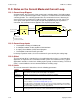
Fast Stop Ramp
Deceleration rate used by the velocity loop when the amplifier is hardware
disabled. Range: 0 to 100,000,000. Default: velocity loop Decel. Limit value.
For more information, see Velocity Loop Limits (p. 122).
Low Gains Shift
Increases the resolution of the units used to express Vp and Vi, providing more
precise tuning. For more information, see Velocity Gains Shift (p. 123).
Hi Gains Shift
Decreases the resolution of the units used to express Vp and Vi, providing more
precise tuning. For more information, see Velocity Gains Shift (p. 123).
Vi Drain (integral
bleed)
Vi drain modifies the effect of velocity loop integral gain. The higher the Vi Drain
value, the faster the integral sum is lowered. Range: 0 to 32,000. Default: 0.
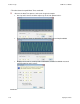
3
Click Close to close screen.