
User guide

CME 2 User Guide Installation, Startup, and Interface Tour
Copley Controls 25
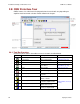
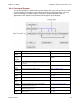
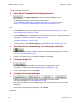
2.8.3: Functional Diagram
The functional diagram, shown below, provides button-click access to most of the screens
used to configure an amplifier. It also indicates the flow of control from input, across all
active control loops, to motor/feedback. Only those control loop buttons that are
appropriate to the amplifier and operational mode appear on the diagram.
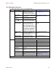
Name
Description
For More Information
Input/
Output
Opens Input/Output screen.
Digital Inputs and Outputs (p. 55)
CVM
Control
Program
Opens Copley Virtual Machine screen.
Copley Indexer Program User’s
Guide.
Input
Command
Opens screen for configuring the input command.
Button label varies depending on the selected control
loop input.
Command Inputs (p. 69)
Control
Loops
Each opens a control loop configuration screen.
Control Loops (p. 111)
Motor/
Feedback
Opens the Motor/Feedback screen.
Motor/Feedback (p. 41)
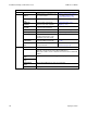
Home
Configure and test homing.
Homing (p. 145)
Configure
Regen
Opens Regen Settings screen.
Regen Resistor Configuration
(p. 213)
Configure
Faults
Opens Fault Configuration screen.
Faults (p. 87)
Configure
Filters
Opens Filter Configuration Screen
Filters (p. 181)
Encoder
Correction
(Stepper amplifier with encoder only.) Opens
Encoder Correction screen.
Encoder Correction (p. 142)
Detent
(Stepper amplifier only). Opens stepper amplifier
Advanced Tuning screen.
Detent Compensation Gain
(p. 143)
Position
Limits
(Stepper amplifier with encoder only.) Opens Position
Limits screen.
Position Limits (Stepper Amplifier)
(p. 140)