
Installation Sheet


®
ASSA ABLOY
FM533 (07/12)
Copyright © 2012 Corbin Russwin Inc., an ASSA ABLOY Group company.
All rights reserved. Reproduction in whole or in part without the express written
permission of Corbin Russwin, Inc. is prohibited.
2 of 4
Mark door
Locate and mark horizontal center line at desired height above
floor. Fold template over edge of door, centering on horizontal
line. Mark centers of holes at proper backset. Mark both sides
o
f the door.
Note:
Be sure to verify backset before marking & drilling door.
Drill door
A. 2-1/8” (54mm) hole thru door. Cut ANSI tab notche s
as shown on template (except CL3350 and CL3370).
B. Drill 1” (25mm) hole in edge of door. Cut out for
latch front 5/32” (4mm) deep. 1-1/8” (29mm) wide
x 2-1/4” (57mm) high. Check latch unit for proper
width front and square or round corners
(except CL3350 and CL3370).
C. Drill two (2) 11/32” (8mm) Dia. holes through door
for all functions.
Caution:
To avoid splintering wood doors, drill holes from both sides.
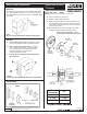
Adjust lock to door thickness
if other than 1-3/4” (44mm)
doors .
*
(Lock pre-set from factory for 1-3/4” door).
A. Remove outside lever (see page 4)
B. Slide off outside cassette assembly.
C. Rotate rose liner to adjust lock to fit door thickness, so
that the distance (Dim. “A”) from the inside of the liner to
the centerline of the retractor is one half of the thickness
of the door (see chart) .
D
. Re-assemble outside cassette assembly onto chassis
a
ssembly (except CL3380 and CL3381 functions).
*
Note: For doors more than 2”, verify
lock package is labeled with “D214” option.
Door
Thickness*
“A”
1-3/4” (44)
2” (50)
2-1/4” (57)
7/8” (22)
1” (25)
1-1/8” (29)
Install Strike
Outside
Rose Liner
Chassis
Assembly
Outside
Cassette
Assembly
Lever
Catch
Door & Frame Preparation
Adjust Lock for Door
Thickness