Warranty Corega International warrants product for two years from date of purchase against defects in materials and workmanship. This warranty does not cover any defects caused by accident, misuse, fair wear and tear, neglect, or an attempt at repair. This warranty is offered as an additional benefit to the consumer’s statutory rights and does not affect these rights in any way.
ADSL WIRELESS 802.
ENGLISH Table of Contents 1 FCC STATEMENT CE DECLARATION OF CONFORMITY MANUFACTURER’S DISCLAIMER STATE 2 2 2 CHAPTER 1.0: GETTING TO KNOW YOUR ADSL WIRELESS ROUTER 1-1 FEATURES OF THE ADSL WIRELESS ROUTER 1-2 CONTENTS OF THE ADSL WIRELESS ROUTER PACKAGE 2 2 2 CHAPTER 2.0: HARDWARE INSTALLATION & SETUP 2-1 CONNECTORS AND INDICATORS 2-2 INSTALLATION 3 3 4 CHAPTER 3.0: BASIC INSTALLATION & SETUP 3-1 GATEWAY USING PPPoE 3-2 GATEWAY USING PPPoA 3-3 MODEM USING LLC ENCAPS. 3-4 GATEWAY USING LLC ENCAPS.
FCC Statement This device complies with Part 15 of FCC rule. Operation is subject to the following two conditions: This device may not cause harmful interference. This device must accept any interference received, including interference that may cause undesired operation. This ADSL Wireless Router has been tested and found to comply with the limits for a Class B digital device, pursuant to Part 15 of the FCC Rules.
2.0 Hardware Installation and Setup 2-1 Connectors and Indicators The rear panel of the router is shown in Figure 2. Figure 2. Rear Panel • • • • • Antenna Reset ADSL LAN 1–4 Power Provides data transmission and reception for wireless devices. Please ensure that the Antenna is facing upwards. Pressing this button for 3 seconds will reset the unit back to factory defaults. This is the WAN connection port to the telephone socket. Four LAN ports for local computers/printers.
Power on the devices in the following sequence: • ADSL Router • Computer(s) Note! The computer needs to be configured with the following: • Ethernet Card supporting either; - 10Base-T - 100Base-TX - 802.11b Wireless • TCP/IP Protocol • Web browser such as Microsoft Internet Explorer 4.0 or later. Note! If you are connecting via a wireless connection – the Access Point in the router is programmed with the following default parameters: SSID - Corega WEP - disabled 3.
The following screen should appear: Figure 5. Login Screen The factory default values are: Username Password Leave blank admin Click OK. ENGLISH The following screen should appear: Figure 6. One Page Setup By setting the parameters on this page, users should then be able to access the internet using the router. • Host Name: This entry is required by certain ISPs. (If not necessary – leave blank). • Domain Name: This entry is required by certain ISPs. (If not necessary – leave blank).
• Channel: Select the appropriate channel number from the drop-down menu. The permissible channels are different in each country due to local government regulations. Make sure that all nodes in the same wireless LAN network use the same channel. • WEP: (Wired Equivalent Privacy), WEP is an encryption mechanism used to protect your wireless data by providing a secure communications method.
3-1 Gateway using PPPoE Figure 8. Gateway using PPPoE • User Name: Enter your ISP Username. • Password: Enter your ISP Password. • Connect-on-demand: Only enable this option if your ISP charges by the megabyte or by minutes (seconds) of line useage. Enabling this option will cause the router to connect to the ADSL line when there is a packet waiting to be transmitted. Set the Max Idle Time with the length of time the router will remain in an idle state before reconnecting to collect incoming data.
3-5 Gateway using LLC Encaps. (Static IP) Figure 10. Gateway using LLC Encaps. (Static IP) Choose this setting according to the following conditions: 1. You want to employ NAT. NAT allows you to use single IP address as the external one to share internet access for all of your PCs, as well as protect them from outside intruders. 2. Your ISP uses LLC Encapsulation and provides you with one or more IP addresses when you apply for the service. You can find more information on RFC 2684.
Specify WAN IP Address: Enter the IP address provided by your ISP. Subnet Mask: Enter the subnet mask values provided by your ISP. Default Gateway IP Address: Your ISP will provide you with the Default Gateway IP Address. Domain Name Server (DNS): Your ISP will provide you with at least one DNS IP Address. Multiple DNS IP settings are common. The first available DNS entry is used in most cases.
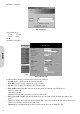
4-2 Virtual Private Network (VPN) Settings A Virtual Private Network (VPN) allows users to use the internet to make the equivalent of a direct connection (private network) between two offices. Private networks should be extremely secure, therefore when using the internet to make a VPN, data encryption must be used to ensure a high level of data security. Figure 15. VPN Settings • Select Tunnel Entry: The router allows the user to set up multiple VPN configurations. Each configuration is called a Tunnel.
2. IP Address: Selecting this item allows only the specific PC with the IP address you enter in the IP field to the Tunnel. Figure 17. Restricting IP Access Refer to the above figure as an example. Only the PC with IP Address 192.168.1.101 will have the access from the local side of Tunnel. Similarly, only the PC with IP Address 192.168.2.51 can access the Tunnel from the other end. 3. IP Range: Selecting this item allows a specific group of PCs access to theTunnel. Figure 18.
By entering the number of seconds in the Key Lifetime field, you may optionally select to have the key expire at the end of the time you specify. Leave this field blank for the key to last indefinitely. Figure 20. Key Timing Manual Keying: This allows you to manually enter the keys to be used for encryption and authentication. Enter the Keys (code) you wish to use for encryption and authentication separately in the “Encryption KEY” and “Authentication KEY” fields.
Key Lifetime: You may optionally select to have the key expire after a period of time that you specify. Enter the number of seconds you’d like the key to be available or leave the field blank for the key to last indefinitely. NetBIOS Broadcast: Check the box to allow NetBIOS traffic pass through the VPN Tunnel. Anti-replay: Check the box to enable this function. This item will keep track of sequence numbers as data packets arrive and ensure security at the IP packet level.
Figure 24. Creating a Tunnel between a VPN router and a VPN client with a dynamic IP address Once you are satisfied that your settings are correct, click the “Apply” button. Click the “Cancel” button to exit the screen without saving any changes. 4-3 DHCP Configuration A DHCP (Dynamic Host Configuration Protocol) Server can automatically assign IP Addresses to each computer in your network. Unless you already have one in your LAN, it is highly recommended that you set your router to act as a DHCP server.
4-4 Web Control This feature allows you to restrict LAN users access to specific web sites. To block a site, you can enter either a complete URL (internet address) or keywords included in the URL. ENGLISH Figure 26. Web Control • Control Web Access: Check “Enable” or “Disable” to make this function active or inactive. • Control Type: Check “Allow” to allow users on the network to access specific websites listed on the location only.
4-6 Access Control The Access Control feature allows administrators to set up to 10 access policies to block or allow certain users from accessing the Internet or specific applications. Before using this function, the network PCs which you want to control the access limitation should be assigned fixed IP Addresses. Figure 28. Access Control Packet Filter: Select the number of policy rules you want to configure. Up to 10 policies can be set.
4-7 Virtual Server Settings The Virtual Server Settings application allows up to a maximum of ten public services that can be accessed by external users over the internet. Service can be applications such as a Web, Email, FTP etc.. Each service is provided by a dedicated network computer (server) configured with a fixed IP Address. Although the internal service addresses are not directly accessible to the external user, the router is capable of identifying the service requested by the service port number.
UPnP Forwarding UPnP (Universal Plug and Play) is a standard introduced from Microsoft and UPnP Forum for interoperability. Currently, this function supported by this device allows you to set virtual server from a Windows OS that supports UPnP, such as Windows XP. UPnP Function: Check “Enable” will allow LAN side PCs that support UPnP to set virtual server. • Before enabling the UPnP Forwarding, ensure that the server computers have been configured with fixed IP Addresses.
4-8 Special Applications Some applications use multiple TCP/UDP ports to transmit data. With NAT enabled, these applications cannot work with the router. Port Triggering allows some of these applications to work properly. Note that only one PC can use each Port Triggering setting at any time. ENGLISH Figure 32. Special Applications • Application name: Enter the name of the application you wish to configure.
Figure 34. DMZ Host DMZ Host 1. Before setting up a LAN PC to act as a DMZ Host, you should configure it using a fixed IP Address. 2. Ensure that the “Private IP Address” of the router is set to the default value of 192.168.1.1. 3. Click the “DMZ Host” option in the Advanced Menu and enter the fixed IP Address of the Exposed Host PC in the “DMZ Host” IP Address location. Entering “0” will disable this application. Multi DMZ 2.
4-11 Static Routing Only users with an excellent understanding of router protocols should attempt to change settings in this area. The Static Routing feature allows PCs that are connected to the LAN side of the router, to communicate with other PCs that are connected to another router. The router supports up to 20 route table entries. Figure 36.
4-12 Wireless This setting page allows you to configure advanced wireless functions. Users wishing to change these values from the defaults should have a thorough understanding of wireless technology. Figure 38. Wireless Settings • Wireless Station Status: The “Active MAC Table” shows the MAC addresses of wireless clients, which have the same SSID and WEP key with router. When the “MAC Filter” function is disabled, the background color is gray.
• Beacon Interval: This is the signal sent periodically by the wireless access point to provide synchronization among the stations in the wireless LAN. • RTS Threshold: RTS packet is used to account for potential hidden stations. This feature allows you to set the size of the RTS packet. • Fragmentation Threshold: If the length of data frame needing transmission exceeds the fragmentation threshold you set in the column, the data frame will be fragmented.
Chapter 5.0: Management 5-1 Device Administration Settings This feature allows the administrator to manage the router by setting certain parameters. For security reasons, it is strongly recommended that you set Passwords so that only authorized persons are able to manage this router. If the Password is left blank, all users on your network can access this router simply by entering the unit’s IP Address into their web browser’s location window. ENGLISH Figure 42.
PPoE Pass Through: Check Enable to allow PPoE packets to pass through the router if there is a LAN PC using PPPoE for data communication with another internet device. Remote Upgrade: Check Enable if you want to allow the authorized remote users to upgrade firmware from WAN side. Reset Device: Select “Yes” if you want to clear a connection, reboot, and re-initialize the unit without affecting any of your configuration setting.
5-3 Log The Log application provides the administrator with the ability to trace internet connection. With viewing the Log information, an administrator can send the record to specific LAN PCs to have the real time monitor. Figure 44. Log Settings Access Log: Check the “Enable” option if you want to activate this function. Send Log: Enter the IP address of the PC that you wish to use to view the Log information. View Log: Click this button to view the log on-line.
5-4 Backup & Restore This function allows you to save the router’s configuration as backup, or retrieve the configuration file you saved before turning the setting back. Figure 45. Backup & Restore Configuration Backup: Click the “Backup” button to save the current configuration as a backup file. Restore: Enter the path of the configuration file you saved on the PC. You can choose “Browsing” to view the folders and select the file. Click “Restore” to retrieve it.
Source IP: You can chose to issue the ping test from the LAN side by selecting the router’s private IP Address or from the WAN side by selecting the router’s WAN IP Address. Destination IP: Enter the IP Address of the destination device you want to ping. If the router’s LAN IP address is selected as Source IP, you can only ping a LAN side device and vice versa. Packet Number: Enter the packet numbers you wish to use to ping the destination device. The maximum numbers are four.
6-2.2 Manual Configuration of Fixed IP Addresses 1. From the “Apple” menu, select “Control Panel” and click on “TCP/IP”. 2. In the “TCP/IP (A New Name For Your Configuration)” window, select “Ethernet” in the “Connect via” location from the drop-down list. 3. In the “Setup” area: - Select “Manually” in the “Configure” location from the drop-down list. In the “IP Address” location, enter the IP Address that you want to assign to the computer. (see the notes on Fixed IP Addresses 2-4 ). Enter “255.255.255.
Chapter 7.0: Trouble Shooting This chapter provides solutions to problems you may encounter during installation and operation of your router. Hardware T: The Power LED is off. - Check the power cable is properly connected to the router, the power adapter and the socket. T: The LAN Link LED is off. - Check the computer, hub or switch is properly connected to the router. - Check the computer’s Ethernet card is properly installed. - Check the router and the computer are on the same network segment.
Appendix A: Frequently Asked Questions Q: What is the maximum number of IP Addresses the router can support? - The router can support up to 253 IP Addresses in the range of 192.168.1.2~192.168.1.254. Q: Where should the router be installed on the network? - In a typical environment, the router should be installed between the ISP and your LAN. Connect the router to the phone jack which supplies the ADSL signal, and connect your PCs to the RJ45 jack on the LAN side.
Appendix B: Technical Specifications Standards Compliance ADSL G.dmt for 8Mbps downstream & 640Kbps upstream ADSL G.lite for 1.5Mbps downstream & 512Kbps upstream IEEE 802.3 10/100BASE-T/TX IEEE 802.
C-2.2 Build 2 Filter Lists: “WinXP Broadband VPN Router” and “Broadband VPN Router WinXP”. [Filter List 1] WinXP Broadband VPN Router 1. In the to_VPNRouter Properties, deselect the Use Add Wizard check box, and then click Add button to create a new rule. 2. From the IP Filter List tab, click the Add button. 3. Type an appropriate name “XP Broadband VPN Router” for the filter list, deselect the Use Add Wizard check box, and then click Add button. 4. In the Source address area, click My IP Address. 5.
Appendix D: Glossary 10Base-T An adaptation of the Ethernet standard for Local Area Networks (LANs). 10Base-T uses a twisted pair cable with maximum lengths of 100 meters. Adapter A device that makes the connection to a network segment, such as Ethernet and modem cards and adapters. ADSL Asymmetric Digital Subscriber Line (ADSL), as it’s name indicates, is an asymmetrical data trasmission technology with higher traffic rate downstream and lower traffic rate upstream.
method used. Local Area Network (LAN) A computer network that spans a relatively small area. Most LANs are confined to a single building or group of buildings. However, one LAN can be connected to other LANs over any distance via telephone lines and radio waves. A system of LANs connected in this way is called a wide area network (WAN). MAC Address Short for Media Access Control Address, a hardware address that uniquely identifies each node of a network.
THIS PAGE IS INTENTIONALLY LEFT BLANK ENGLISH 36
ENGLISH THIS PAGE IS INTENTIONALLY LEFT BLANK 37
THIS PAGE IS INTENTIONALLY LEFT BLANK ENGLISH 38