Warranty Corega International warrants product for two years from date of purchase against defects in materials and workmanship. This warranty does not cover any defects caused by accident, misuse, fair wear and tear, neglect, or an attempt at repair. This warranty is offered as an additional benefit to the consumer’s statutory rights and does not affect these rights in any way.
ADSL WIRELESS 802.
ENGLISH Table of Contents 1 FCC STATEMENT CE DECLARATION OF CONFORMITY MANUFACTURER’S DISCLAIMER STATE 2 2 2 CHAPTER 1.0: GETTING TO KNOW YOUR ADSL WIRELESS ROUTER FEATURES OF THE ADSL WIRELESS ROUTER 1-1 CONTENTS OF THE ADSL WIRELESS ROUTER PACKAGE 1-2 3 3 3 CHAPTER 2.0: HARDWARE INSTALLATION & SETUP 2-1 CONNECTORS AND INDICATORS INSTALLATION 2-2 4 4 5 CHAPTER 3.
FCC Statement This device complies with Part 15 of FCC rule. Operation is subject to the following two conditions: This device may not cause harmful interference. This device must accept any interference received, including interference that may cause undesired operation. This ADSL Wireless Router has been tested and found to comply with the limits for a Class B digital device, pursuant to Part 15 of the FCC Rules.
Chapter1.0 Getting to know your ADSL Wireless Router 1-1 Features of the ADSL Wireless Router Congratulations on your purchase of this ADSL Wireless Router. The router provides the following benefits: • • • • • • • • • High Speed internet Access over ADSL (Up to 8Mbps internet downstream speed and 832Kbps upstream speed). Allows multiple computers to share a single ISP internet account. Wireless LAN connection via integrated Wireless Access Point.
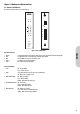
Chapter 2.0 Hardware Installation and Setup 2-1 Connectors and Indicators The front and rear panels of the router are shown in Figure 2. Power Status 100 ADSL 10 RESET 1 2 LAN LAN1 3 4 ADSL LAN2 Wireless LAN3 LAN4 WLBAR-AA Wireless, ADSL Broadband Access Router POWER Figure 2. Front & Rear Panels. • • • • • Antenna Reset ADSL LAN 1–4 Power Provides data transmission and reception for wireless devices. Please ensure that the Antenna is facing upwards.
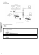
2-2 Installation Connect the router as shown. Figure 3. Hardware Installation ENGLISH Power on the devices in the following sequence: • ADSL Router • Computer(s) Note! The computer needs to be configured with the following: • Ethernet Card supporting either; - 10Base-T - 100Base-TX - 802.11b or 802.11g Wireless • TCP/IP Protocol • Web browser such as Microsoft Internet Explorer 4.0 or later.
Chapter 3.0 Basic Installation & Setup This chapter describes the procedures necessary to configure the basic functions of the router to allow internet access.
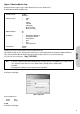
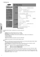
ENGLISH 3-1 One Page Setup Figure 5. One Page Setup By setting the parameters on this page, users should then be able to access the internet using the router. General • Host Name: This entry is required by certain ISPs. (If not necessary – leave blank). • Domain Name: This entry is required by certain ISPs. (If not necessary – leave blank). • Private IP Address: This is the LAN IP address of the router. This is the address that is used to configure the router. The default values are: 192.168.0.
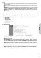
VC Setting: • VPI: If you have uploaded a config file (see section 5.6 on page 39, this parameter will already be set. This is a value between 0-255 and is provided by your Internet Service Provider (ISP). • VCI: If you have uploaded a config file, this parameter will already be set. This is a value between 32-65535 and is provided by your Internet Service Provider (ISP).
3-1-2 Gateway using PPPoA Figure 7. Gateway using PPPoA • Login Name: Enter your ISP Username. • Password: Enter your ISP Password. • Connect-on-demand: Only enable this option if your ISP charges by the megabyte or by minutes (seconds) of line usage. Enabling this option will cause the router to connect to the ADSL line when there is a packet waiting to be transmitted. Set the Max Idle Time with the length of time the router will remain in an idle state before reconnecting to collect incoming data.
3-1-4 Gateway using Static IP Figure 9. Gateway using Static IP Choose this setting according to the following conditions: 1. You want to employ NAT. NAT allows you to use single IP address as the external one to share internet access for all of your PCs, as well as protect them from outside intruders. 2. Your ISP uses LLC Encapsulation and provides you with one or more IP addresses when you apply for the service. You can find more information on RFC 2684.
3-1-6 Modem using LLC Encaps Figure 11. Modem Only Choose this setting according to the following conditions: 1. You want this device acting as an ADSL modem. 2. Your ISP uses LLC encapsulation. Your ISP may use DHCP to provide an IP address or to provide you with one or more IP addresses, as well as asking you to use PPPoA or PPPoE connection modes when you apply for the service. However, as you have chosen to make this device act as an modem, you have to know how to configure your PCs.
3.2 Configure Wireless Security. From the One-Page-Setup screen, select the Configure option from under the wireless section. Figure 12. Configuring Wireless Security The default wireless security setting is “disabled”. This is to ensure that all wireless devices can initially connect to the router. It is recommended that you enable wireless security on the router. Select either WEP or WPA-PSK security. All devices must use the same method of encryption.
3-2-2 WPA-PSK Encryption WPA is a wireless security system with far greater protection than WEP. It avoids most of WEP’s vulnerabilities. WPA has significant advantages over WEP. The encryption key used to encrypt the data is different for every packet. This TKIP (Temporal Key Integrity Protocol) mechanism shares a starting key between devices. Each device then changes their encryption key for every packet. It is extremely difficult for hackers to read messages, even if they have intercepted the data.
3-3 Status The Status page shows the status of the router. Modem • Modem Status Possible options are “Connecting” (when establishing an ADSL connection) and “Connected” (when the ADSL link is active). • DownStream Connection Speed This is the speed of the ADSL link from the ISP to the router. The actual speed is dependent upon a number of parameters including your distance from the ISP’s ADSL equipment, and the number of other users also connected to their equipment.
Chapter 4.0 Advanced Configuration Most users will not need to change any advanced configuration on this router. This section is intended for users who are familiar with both wireless and routers. 4-1 DHCP Configuration A DHCP (Dynamic Host Configuration Protocol) Server can automatically assign IP Addresses to each computer in your network. Unless you already have one in your LAN, it is highly recommended that you set your router to act as a DHCP server. ENGLISH Figure 15.
4-2 DMZ In computer networks, a DMZ (Demilitarized Zone) is a computer host or small network inserted as a “neutral zone” between a company’s private network and the outside public network. It prevents outside users from getting direct access to computers on the local LAN. The firewall protects computers on the local LAN from unauthorised access from computers on the ADSL WAN port or the Internet. However, some applications (such as games) require a less secure network for them to interoperate.
4-3 Firewall Rules This allows users to configure the Stateful Packet Inspection Firewall to protect the user from external hackers. The firewall is enabled as default to provide the user with the maximum protection. Most users should not have to make any changes to the firewall Figure 17.
4-4 Firewall Services This section allows advanced users to create user defined services for use with the firewall. The following services are programmed as standard. TCP/UDP Ports FTP H.
4-5 Internet Access Control Internet Access Control allows the network administrator the ability to allow computers on the local or wireless LANs access (or denial) to specify websites or server types. Figure 18. Internet Access Control Main Settings URL Filter: Select from one of the thee options. • Disable URL Filter: In this mode, the router performs no filtering. • Block Always: In this mode, the URL filters set will be active continually. See section 4-5-1 for details on setting the filters.
4-5-1 Internet Access Control - URL Filter Setting From the Internet Access Control screen, select the Configure URL Filter option. Figure 19. Internet Access Control - URL Filter • Delete: Highlight a filter string in the Current Filter Strings box, then press Delete to remove the filter. • Delete All: Press to remove all current filters. ENGLISH To add a word string to be checked when filtering, enter the characters in the Add Filter String and then press Add.
4-6 Port Forwarding (Virtual Server) Settings The Virtual Server Settings application allows up to a maximum of ten pre-defined public services and up to five user-defined services that can be accessed by external users over the internet. Service can be applications such as a Web, Email, FTP etc. Each service is provided by a dedicated network computer (server) configured with a fixed IP Address.
4-7 Dynamic DNS (DDNS) “DDNS” is an acronym for Dynamic Domain Name Service. Whenever you set up the web servers, mail servers, or sometimes ftp servers, you need “Domain Name” to help internet users reach your servers easily. The internet actually runs on IP Addresses which are in numerical order, for example “66.37.215.53”. These IP Addresses identify the location of each device connected to the internet.
4-8 Special Applications ENGLISH This feature is for Internet applications which normally cannot work through the built-in firewall. If an Internet application does not work, you can try defining it here. You will need detailed information about the application from the provider of the service or application. Note that the terms "Incoming" and "Outgoing" refer to traffic from the client (PC) viewpoint. Figure 22. Special Applications Operation is as follows: 1.
4-9 Miscellaneous Options This section allows users to configure some Miscellaneous options in the router. Figure 23. Miscellaneous Options • Respond to Ping: If this option is enabled, then the router will respond to a ping request on the LAN port. This option is sometimes useful when you want to test connections across the Internet. When disabled, the router will not respond, making the network more secure. • MTU Size: This is the Maximum Transmission Unit size.
4-10 Routing The Routing feature allows the router to exchange routing information with other routers in the network. Figure 24.
4-11 Time Schedule This feature allows you to limit connection availability according to a nominated time of day schedule. Up to two active sessions are allow on each day of the week. • Sessions: For each day of the week, the user can define up to two time periods when the schedule will be active. The schedule is used in conjunction with Internet Access Control as described in section 4-5. ENGLISH Figure 25.
4-12 Wireless Access Control Wireless Access Control provides an additional level of security allowing the network administrator to block unauthorised wireless clients from connecting to the router. Figure 26. Wireless Access Control Station Access ALL Wireless Stations: If this is selected, then all wireless clients can connect to the router without any additional security. Trusted Wireless stations only: If this is selected, then only wireless clients that have been authorised can connect to the router.
4-13 Virtual Private Network (VPN) Settings A Virtual Private Network (VPN) allows users to use the internet to make the equivalent of a direct connection (private network) between two offices. Private networks should be extremely secure, therefore when using the internet to make a VPN, data encryption must be used to ensure a high level of data security. Figure 28. VPN Policies The table shows all the current VPN Policies enabled on the router.
ENGLISH 4-13-1 Add Manual Policy Figure 29. Adding a Manual VPN General • Policy Name: The router allows the user to set up multiple VPN configurations. Each configuration has a unique name. Note! The Policy Name set here does not always have to match the name used at the other end of the Tunnel. However, certain VPN applications require a Tunnel to have the same name at both ends of the Tunnel.
Remote LAN • IP Address: This allows the Remote LAN VPN to be directed to either - Single PC Use this when the remote device is a single PC using Dynamic IP and with no LAN. • IP Address Leave blank. Leave blank. • Subnet Mask - IP Address • IPAddress • Subnet Mask Enter the IP address of the single device on the Remote LAN that can access the VPN. Not Applicable - Subnet Address • IP Address • Subnet Mask Enter the IP address of the Remote LAN that can access the VPN.
ENGLISH 4-13-2 Add Auto Policy Figure 30. Adding an Auto VPN General • Policy Name: The router allows the user to set up multiple VPN configurations. Each configuration has a unique name. Note! The Policy Name set here does not always have to match the name used at the other end of the Tunnel. However, certain VPN applications require a Tunnel to have the same name at both ends of the Tunnel.
Remote LAN • IP Address: This allows the Remote LAN VPN to be directed to either - Single PC Use this when the remote device is a single PC using Dynamic IP and with no LAN. • IP Address Leave blank. Leave blank. • Subnet Mask - IP Address • IPAddress • Subnet Mask Enter the IP address of the single device on the Remote LAN that can access the VPN. Not Applicable - Subnet Address • IP Address • Subnet Mask Enter the IP address of the Remote LAN that can access the VPN.
Chapter 5-0 Management Topics dealt with in this section are to do with the management of the router. 5-1 PC Database The PC Database contains a list of all the computers attached to the local LAN and wireless LAN. This database performs the following functions: ENGLISH It maintains a list of all the DHCP Clients which have been allocated a Dynamic IP address by the router. The router will allocate the same Dynamic IP address to clients when they reconnect.
5-1-1 Advanced Administration This allows the user to add computers with Fixed IP addresses to the PC Database or to add a computer to the list which are not connected to the the local LAN. Properties • Name: Enter a name of the computer that you wish to add to the database. • Address: Enter either the reserved DHCP address or the Fixed IP address that you wish this computer to use.
5-2 Password This feature allows the administrator to manage the router’s password. For security reasons, it is strongly recommended that you set Passwords so that only authorized persons are able to manage this router. If the Password is left blank, all users on your network can access this router simply by entering the unit’s IP Address into their web browser. ENGLISH Figure 33. Password 35 • Old Password: The existing password must be entered before the password can be changed.
5-3 Remote Administration This feature allows the router to be managed from a device on the Internet. (i.e. via the ADSL WAN port). Figure 34. Remote Administration Remote Administration • Enable: Check the tickbox to allow the router to be managed via the Internet. If disabled, the router will not respond to requests via the ADSL WAN port. • Port Number: Enter a value between 1024 and 65535. The default value is 8080. Normal HTTP (web) connections will use port 80.
5-4 Network Diagnostics ENGLISH Figure 35. Network Diagnostics Ping This function allows you to test the connection between the router and LAN or between the router and internet. • IP Address: Enter an IP address of a device which is either on the Local LAN or on the WAN. Then click Ping. DNS Lookup This function allows you to look up the address of a Domain Name of URL using a Domain Name Server. (Note that the DDNS must be setup for this to work - see section 4-7.
5-5 Logs The Log application provides the administrator with the ability to trace internet connections. When viewing the Log information, an administrator can send the record to specific LAN PCs to have real time monitoring. ENGLISH Figure 36. Log Settings Logs This shows the current log file for the router. • Refresh: Clicking this box refreshes the log screen to show the most recent entries. • Clear Log: Clicking this box deletes all the entries in the log.
5-6 E-Mail ENGLISH This allows the status of the router to be emailed to a specific email account. Figure 37. E-Mail Settings E-mail Notification • Turn E-mail Notification on: Check this box if you wish to enable email notification. • Send this to E-mail Address: Enter the email address of the user that wishes to receive the notification.
5-7 Config File This function allows you to save the router’s configuration as backup, or retrieve the configuration file you saved before turning the setting back. ENGLISH Figure 38. Backup & Restore Configuration • Backup Config : Click the “Backup” button to save the current configuration as a backup file. You will be asked where you want to store the file on your local computer. • Restore Config: Enter the path of the configuration file you saved on the PC.
5-8 Upgrade Firmware ENGLISH This setting page allows you to upgrade to the latest version of firmware to keep your router up-to-date. Before you upgrade the firmware, you have to get the latest firmware and save it on the PC you use to configure the router. Figure 39. Upgrade Firmware Page • Select a file to upgrade: Enter the path of the latest firmware you saved on the PC. You can choose “Browsing” to view the folders and select the firmware.
Chapter 6.0: Trouble Shooting This chapter provides solutions to problems you may encounter during installation and operation of your router. Hardware Q: The Power LED is off. - Check the power cable is properly connected to the router, the power adapter and the socket. Q: The LAN Link LED is off. - Check the computer, hub or switch is properly connected to the router. - Check the computer’s Ethernet card is properly installed. - Check the router and the computer are on the same network segment.
Appendix A: Frequently Asked Questions Q: What is the maximum number of IP Addresses the router can support? - The router can support up to 253 IP Addresses in the range of 192.168.0.2~192.168.0.254. Q: Where should the router be installed on the network? - In a typical environment, the router should be installed between the ISP and your LAN. Connect the router to the phone jack which supplies the ADSL signal, and connect your PCs to the RJ45 jack on the LAN side.
Appendix B: Technical Specifications Standards Compliance ADSL G.dmt for 8Mbps downstream & 640Kbps upstream ADSL G.lite for 1.5Mbps downstream & 512Kbps upstream IEEE 802.3 10/100BASE-T/TX IEEE 802.11g Wireless IEEE 802.