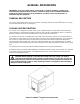
AURORAR10,000 PLUS COOLING UNIT Installation Manual Part No. 300614000 November 8, 1989 Revised: April 12, 1993 THIS DOCUMENT CONTAINS IMPORTANT INFORMATION This Manual must be read and understood before installing or operating this equipment Ó IMI CORNELIUS INC; 1989--93 PRINTED IN U.S.
TABLE OF CONTENTS Page GENERAL INFORMATION . . . . . . . . . . . . . . . . . . . . . . . . . . . . . . . . . . . . . . . . . . . . . . . . . . 1 GENERAL DESCRIPTION . . . . . . . . . . . . . . . . . . . . . . . . . . . . . . . . . . . . . . . . . . . . . . COOLING UNIT DESCRIPTION . . . . . . . . . . . . . . . . . . . . . . . . . . . . . . . . . . . . . . . . . 1 1 SYSTEM THEORY OF OPERATION . . . . . . . . . . . . . . . . . . . . . . . . . . . . . . . . . . . . . INSTALLATION . . . . . . . . . . . . .
TABLE OF CONTENTS (cont’d) Page ADJUSTING CO2 REGULATORS . . . . . . . . . . . . . . . . . . . . . . . . . . . . . . . . . . . ADJUSTING DISPENSING VALVES WATER FLOW RATE . . . . . . . . . . . . . 14 14 ADJUSTING WATER-TO-SYRUP ‘‘RATIO’’OF DISPENSED PRODUCT . ADJUSTING SIZE OF DRINK DISPENSED . . . . . . . . . . . . . . . . . . . . . . . . . . . REPLENISHING CO2 SUPPLY . . . . . . . . . . . . . . . . . . . . . . . . . . . . . . . . . . . . . . . . . . REPLENISHING SYRUP SUPPLY . . . . . . . . . . . . . .
TABLE OF CONTENTS (cont’d) Page COOLING UNIT CO2 INLET LINE CO2 GAS CHECK VALVE . . . . . . . . . . . TROUBLESHOOTING . . . . . . . . . . . . . . . . . . . . . . . . . . . . . . . . . . . . . . . . . . . . . . . . . . . . . . WATER-TO-SYRUP ‘‘RATIO’’OF DISPENSED DRINK TOO LOW OR TOO HIGH. . . . . . . . . . . . . . . . . . . . . . . . . . . . . . . . . . . . . . . . . . . . . . . . . . . . . . . . . . . . . . . . .
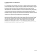
GENERAL INFORMATION IMPORTANT: To the user of this manual - This manual is a guide for installing, operating, and maintaining this equipment. Refer to Table of Contents for page location of detailed information pertaining to questions that arise during installation, operation, service and maintenance, or troubleshooting this equipment.
Table 1. Design Data COOLING UNIT DATA Model No. Overall Dimensions: Height Width Depth 416654 25-inches 36-1/2 inches 24-1/2 inches NOTE: Overall dimensions if Cooling Unit is placed on optional Cooling Unit Stand (P/N 309309069).
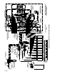
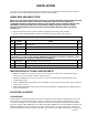
SYSTEM THEORY OF OPERATION (see Figure 2) A CO2 cylinder delivers carbon dioxide gas (CO2) to primary CO2 regulator assembly which deliver regulated CO2 gas to adjustable secondary CO2 regulators. Secondary CO2 regulators delivers regulated CO2 gas to the carbonated water tank inside the Cooling Unit and also to the soft drink tanks. Plain water enters the Cooling Unit and is pumped through and is pre-cooled by the refrigerated Hydro Boostâ coil.
300614000 4 CO2 CYLINDER SUGAR SYRUP CO2 REGULATOR DIET SYRUP CO2 REGULATOR WATER FILTER ASS’Y CO2 GAS CHECK VALVE(10) LIQUID CHECK VALVE COOLING UNIT MODEL: 416654 CO2 CHECK VALVE HYDRO BOOSTR COIL HYDRO BOOSTR BYPASS SHUTOFF VALVE TO DISPENSING STATION CARBONATED WATER TANK ASS’Y COOLING UNIT FIGURE 2.
INSTALLATION This section covers unpacking and inspection, selecting location, installing the Cooling Unit and the Remote Condenser Coil and Fan Assembly preparing for operation, and operation. UNPACKING AND INSPECTION NOTE: The Cooling Unit and the Remote Condenser Coil and Fan Assembly were thoroughly inspected before leaving the factory and the carrier has accepted and signed for them.
fused as indicated on the Unit nameplate. The power circuit may also be wired through an equivalent HACR type circuit breaker rather then the disconnect switch.
CONNECTING ELECTRICAL POWER CIRCUIT TO COOLING Unit (see Figures 5 and 9) IMPORTANT: Before 208/230VAC single-phase 60Hz electrical power circuit is connected to the cooling unit, service power voltage entering the building must be identified. Service power voltage entering the building will either be 208 or 230VAC and may be posted on the main service box. If not, the installer must contact the local electrical power company for information.
CONNECTING ELECTRICAL POWER CIRCUIT TO REMOTE CONDENSER COIL AND FAN ASS’Y (see Figure 5 and 9) CAUTION: The Cooling Unit refrigeration system is cooled by a Remote Condenser Coil and Fan Assembly (P/N 309602000) that is authorized by IMI Cornelius Inc. Use of an unauthorized Remote Condenser Coil and Fan Assembly will automatically void the Cooling Unit factory warranty. NOTE: Electrical power circuit may be connected to the Remote Condenser Coil and Fan Assembly (P/N 309602000) in two ways.
2. Connect flexible plain water inlet supply line (1/2-inch I.D. min.), meeting water inlet supply line requirements of preceding CAUTION note, to Cooling Unit 3/8-in. flare (5/8-18) bulkhead fitting on back of Unit labeled ‘‘WATER INLET’’. DO NOT OPEN WATER INLET SUPPLY LINE SHUTOFF VALVE AT THIS TIME. CONNECTING CO2 INLET SUPPLY LINE TO COOLING UNIT (see Figure 2) WARNING: CO2 displaces oxygen.
18-- IN. 18-- IN. COOLING UNIT 18-- IN. AIR FLOW (OPEN TO ROOM) FIGURE 4. COOLING UNIT SPACE REQUIRED PLACING COOLING UNIT IN OPERATING POSITION 1. Very carefully, move Cooling Unit back into operating position leaving space around Unit (see Figure 4) as specified in SELECTING LOCATION. MAKE SURE THERE ARE NO KINKS IN COOLING UNIT INLET LINES, AND (IF APPLICABLE) REMOTE CONDENSER AND FAN ASSEMBLY REFRIGERATION LINES.
5. Adjust carbonator secondary CO2 regulator (see Figure 2) to a nominal 90-psi. Loosen CO2 regulator adjusting screw locknut. Turn adjusting screw to the right (clockwise) until regulator gage registers nominal 90-psi, then tighten adjusting screw lock nut. CO2 PRESSURE TO CARBONATORS MUST NOT EXCEED 120-PSIG.
Low-Calorie (diet) Syrup Soft Drink Tank CO2 Regulator. Adjust low-calorie (diet) soft drink tank secondary CO2 regulator for low-calorie drink at 10-psig for syrup lines up to 30-feet in length. Syrup lines longer than 30-feet in length may require a slightly higher CO2 regulator setting to 12-psig maximum. Excessive CO2 pressure may cause low-calorie syrup carbonation resulting in foam. IMPORTANT: Syrup systems must be sanitized as instructed before syrup is connected into syrup systems. 11.
OPERATORS INSTRUCTIONS This section covers operating controls, daily pre-operation check, adjustments, replenishing CO2 and syrup supplies, cleaning and sanitizing, Cooling Unit maintenance, Remote Condenser Coil and Fan Assembly maintenance, lubrication, and servicing CO2 gas check valves. WARNING: Disconnect electrical power to Cooling Unit and Remote Condenser Coil and Fan Assembly to prevent personal injury before attempting any internal maintenance.
DAILY PRE-OPERATION CHECK 4. Make sure CO2 cylinder regulator assembly 1800-psi gage indicator is not in shaded (‘‘change CO2 cylinder’’) portion of dial. If so, CO2 cylinder is almost empty and must be replaced. 5. Sufficient syrup supply in all soft drink tanks. If not, replenish syrup supply as instructed. ADJUSTMENTS ADJUSTING CO2 REGULATORS CO2 regulators should be periodically checked for proper pressure settings and if necessary, adjusted as instructed.
SANITIZING SYRUP SYSTEMS Syrup systems should be sanitized every 90 days as instructed following Sanitizer Manufacturer’s recommendations. COOLING UNIT MAINTENANCE COOLING UNIT AIR INTAKE AND EXHAUST FILTERS CAUTION: Air filters on the Cooling Unit must be removed and cleaned every 30 days as instructed. Excessive accumulation of dust, lint, and grease on the air filters will restrict airflow through the Unit which will cause the refrigeration system to overheat.
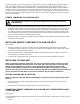
REMOTE CONDENSER COIL AND FAN ASS’Y MAINTENANCE (see Figure 5) CAUTION: Remote Condenser Coil and Fan Assembly connected to the Cooling Unit is equipped with a condenser coil that must be cleaned every 30-days. Allowing condenser coil to become clogged will cause refrigeration system to overheat which will automatically shut refrigeration system down. After condenser coil has been cleaned, high-pressure cutout sensing switch (see Figure 5) will have to be pressed to restart refrigeration system.
SERVICE AND MAINTENANCE The Remote Rooftop Condenser Coil and Fan Assembly Condenser Coil must be cleaned every 30 days. Circulating air, required to cool the coil, is drawn in at bottom and is exhausted out through top of Unit. Clean the condenser coil as follows: 1. Disconnect electrical power to Cooling Unit at disconnect switch, then disconnect electrical power from Remote Condenser Coil and Fan Assembly at disconnect switch. 2.
REMOTE CONDENSER COIL AND FAN ASSEMBLY MAINTENANCE CAUTION: Remote Condenser Coil and Fan Assembly connected to this Cooling Unit is equipped with a condenser coil that must be cleaned every 30-days. Allowing condenser coil to become clogged will cause refrigeration system to overheat which will automatically shut refrigeration system down. After condenser coil has been cleaned, high-pressure sensing cutout switch (see Figure 5) must be pressed to restart refrigeration system.
Note: If your Cooling Unit is equipped with a water tank water level float control, close shutoff valve in plain water inlet supply line. 3. Make sure end of water tank drain hose is routed to floor drain, then remove plug from end of hose and allow water to drain from tank. CAUTION: Never use an ice pick or other instruments to remove ice from evaporator coils. Such practice can result in punctured refrigeration circuit. 4. Allow ice bank to melt. Hot water may be used to speed melting. 5.
REMOTE CONDENSER COIL AND FAN ASS’Y FIGURE 5.
8. Wipe each part with clean lint-free cloth. Inspect each part, especially the ball, for burrs, nicks, corrosion, deterioration, and other damage. Discard ball seat and any damaged or suspicious parts and replace with new parts during reassemble. 9. Reassemble check valves as shown in Figure 6. ALWAYS install new ball seat (QUAD RING) (P/N 312418-000.
Sugar Syrup Soft Drink Tanks CO2 Regulators. Adjust sugar syrup soft drink tanks secondary CO2 regulator at 40-psig for syrup lines up to 10-feet in length plus one pound for each additional length of 10-feet, plus one pound for each 2-feet of vertical lift.
2. Wash drip tray in place on the Unit, then rinse drip tray with hot water allowing water to drain out through the drain hose. 3. Wash cup rest, then rinse the cup rest with clean water. Install cup rest in the drip tray. 4. Clean all external surfaces of the Unit with a sponge. Rinse out the sponge with clean water, then wring excess water out of the sponge and wipe off all external surfaces on the Unit. Wipe Unit dry with a clean soft cloth. DO NOT USE ABRASIVE CLEANERS. 5.
7. Remove detergent solution source from the syrup system. STEP 2. FLUSH SYRUP SYSTEMS 8. Syrup Tank Systems. Connect syrup tank containing potable water, pressurized at 60 to 80-psi, into one of the syrup systems. Bag-in-Box Syrup System. Fill five-gallon container with potable water, then place all bag-in-box syrup containers syrup outlet tubes in container containing potable water. 9. Flush detergent solution out of the syrup system and dispensing valve as follows: A.
WARNING: Flush sanitizing solution from the syrup systems as instructed. Residual sanitizing solution left in the syrup systems could create a health hazard. 18. Fill syrup tank (syrup tank system) or a five-gallon container (bag-in-box system) with potable water. 19. Syrup Tank Systems. Connect syrup tank containing potable water, pressurized at 60 to 80-psi, into one of the syrup systems. Bag-in-Box Syrup System.
REPLENISHING CO2 SUPPLY WARNING: CO2 displaces oxygen. Strict attention must be observed in the prevention of CO2 (carbon dioxide) gas leaks in the entire CO2 and soft drink system. If a CO2 gas leak is suspected, particularly in a small area, immediately ventilate the contaminated area before attempting to repair the leak. Personnel exposed to high concentration of CO2 gas will experience tremors which are followed rapidly by loss of consciousness and suffocation.
3. Connect full tank of syrup into syrup system. SYRUP FLAVOR CHANGE 1. Perform sanitizing procedure on syrup system syrup flavor change will be made on. 2. Check soft drink tank quick disconnects for sticky or restricted operation. Wash disconnects in warm water. 3. Connect full tank of new flavor syrup into syrup system.
REFRIGERATION LINES CONNECTED BETWEEN COOLING UNIT AND REMOTE CONDENSER COIL AND FAN ASS’Y MUST NOT EXCEED 50-- FEET IN LENGTH. REMOTE CONDENSER COIL AND FAN ASS’Y REFRIGERATION LINES VERTICAL RISE MUST NOT EXCEED 20-- FEET. FIGURE 8.
29 300614000 FIGURE 9.
TROUBLESHOOTING IMPORTANT: Only qualified personnel should service internal components or electrical wiring. WARNING: If repairs are to be made to a product system, remove quick disconnects from the applicable product tank, then relieve the system pressure before proceeding. If repairs are to be made to the CO2 system, stop dispensing, shut off the CO2 supply, then relieve the system pressure before proceeding.
Trouble Probable Cause Remedy ADJUSTMENT OF DISPENSING VALVE SYRUP FLOW REGULATOR DOES NOT DECREASE TO DESIRED WATER-TO- SYRUP ‘‘RATIO’’. A. Dirty or inoperative piston or cylinder in dispensing valve syrup flow regulator. A. Disassemble and clean dispensing valve syrup flow regulator. DISPENSED PRODUCT CARBONATION TOO LOW. A. Carbonator CO2 regulator out of adjustment for existing water conditions or temperature. A. Adjust carbonator CO2 regulator as instructed. B.
Trouble Probable Cause Remedy ONLY CARBONATED WATER DISPENSED (con’t). E. Dispensing valve syrup flow regulator, soft drink tank quick disconnect, or syrup lines restricted. E. Sanitize syrup system as instructed. ONLY SYRUP DISPENSED. A. Plain water inlet supply line shutoff valve closed. A. Open plain water inlet supply line shutoff valve. B. CARBONATOR MOTOR power switch in ‘‘OFF’’ position. B. Place switch in ‘‘ON’’position. C. Water filter clogged. C. Replace water filter. A.
Trouble ERRATIC CYCLING OF CARBONATOR (con’t). WATER PUMP MOTOR OPERATES BUT WATER PUMP DOES NOT PUMP WATER. WATER PUMP CAPACITY TOO LOW. Probable Cause Remedy C. Liquid level sensing probe wired wrong. C. Correct liquid level sensing probe wiring. D. Dirty or oily liquid level sensing probe. D. Clean liquid level sensing probe. A. Water inlet supply line shutoff valve closed. A. Open water inlet supply line shutoff valve. B. Kinked water inlet supply line. B.
Trouble COMPRESSOR DOES NOT OPERATE (con’t). Probable Cause Remedy J. Inoperable control board J. Replace control board. K. Inoperable contactor K. Replace contactor. L. No voltage to control board. L. Check for loose or broken wiring. Check 240/24 VAC power transformer for 24 VAC output. (see NOTE below). M. Inoperable control board or water/ice sensor PC board. M. Replace control board. N. Inoperable ICE SENSOR. N. Replace ICE SENSOR. O.
Trouble COMPRESSOR OPERATES CONTINUOUSLY BUT DOES NOT FORM SUFFICIENT ICE BANK (con’t). Probable Cause E. Inoperative control board. No output from board to solenoids. Remedy E. Check LED’s on control board to see if they are modulating. Check for 24V output to pulse modulating expansion valve (see WIRING DIAGRAM). If control board green LED is on and yellow LED Is flashing; but no 24V output, replace board. CONDENSER FAN MOTOR NOT OPERATING AGITATOR MOTOR NOT OPERATING. A. Blown power circuit fuse.
WARRANTY IMI Cornelius Inc. warrants that all equipment and parts are free from defects in material and workmanship under normal use and service. For a copy of the warranty applicable to your Cornelius, Remcor or Wilshire product, in your country, please write, fax or telephone the IMI Cornelius office nearest you. Please provide the equipment model number, serial number and the date of purchase. IMI Cornelius Offices AUSTRALIA D P.O.
THIS PAGE LEFT BLANK INTENTIONALLY 37 300614000
IMI CORNELIUS INC.