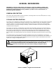
IMI CORNELIUS INC g One Cornelius Place g Anoka, MN 55303-6234 Telephone (800) 238-3600 Facsimile (612) 422-3246 Installation Manual AURORAR10,000 PLUS COOLING UNIT IMPORTANT: TO THE INSTALLER. It is the responsibility of the Installer to ensure that the water supply to the dispensing equipment is provided with protection against backflow by an air gap as defined in ANSI/ASME A112.1.2-1979; or an approved vacuum breaker or other such method as proved effective by test.
TABLE OF CONTENTS Page GENERAL INFORMATION . . . . . . . . . . . . . . . . . . . . . . . . . . . . . . . . . . . . . . . . . . . . . . . . . . 1 GENERAL DESCRIPTION . . . . . . . . . . . . . . . . . . . . . . . . . . . . . . . . . . . . . . . . . . . . . . COOLING UNIT DESCRIPTION . . . . . . . . . . . . . . . . . . . . . . . . . . . . . . . . . . . . . . . . . 1 1 SYSTEM THEORY OF OPERATION . . . . . . . . . . . . . . . . . . . . . . . . . . . . . . . . . . . . . 3 STANDARD COOLING UNIT. . . . . . . .
TABLE OF CONTENTS (cont’d) Page REFRIGERATION SYSTEM TEMPERATURE SENSING DEVICE AND HIGH-PRESSURE CUTOUT SWITCH . . . . . . . . . . . . . . . . . . . . . . . . . . . . . . . 13 DAILY PRE-OPERATION CHECK . . . . . . . . . . . . . . . . . . . . . . . . . . . . . . . . . . . . . . . . ADJUSTMENTS . . . . . . . . . . . . . . . . . . . . . . . . . . . . . . . . . . . . . . . . . . . . . . . . . . . . . . . ADJUSTING CO2 REGULATORS . . . . . . . . . . . . . . . . . . . . . . . . . . . . . . . . . . .
TABLE OF CONTENTS (cont’d) Page COOLING UNIT CO2 INLET LINE CO2 GAS CHECK VALVE . . . . . . . . . . . TROUBLESHOOTING . . . . . . . . . . . . . . . . . . . . . . . . . . . . . . . . . . . . . . . . . . . . . . . . . . . . . . 28 33 WATER-TO-SYRUP ‘‘RATIO’’OF DISPENSED DRINK TOO LOW OR TOO HIGH . . . . . . . . . . . . . . . . . . . . . . . . . . . . . . . . . . . . . . . . . . . . . . . . . . . . . . . . . . . .
TABLE OF CONTENTS (cont’d) Page LIST OF TABLES TABLE 1. DESIGN DATA . . . . . . . . . . . . . . . . . . . . . . . . . . . . . . . . . . . . . . . . . . . . . . . 2 TABLE 2. LOOSE-SHIPPED PARTS . . . . . . . . . . . . . . . . . . . . . . . . . . . . . . . . . . . . .
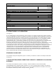
GENERAL INFORMATION IMPORTANT: To the user of this manual - This manual is a guide for installing, operating, and maintaining this equipment. Refer to Table of Contents for page location of detailed information pertaining to questions that arise during installation, operation, service and maintenance, or troubleshooting this equipment.
Table 1. Design Data COOLING UNIT DATA Cooling Unit Model Numbers; 60 HZ UNIT: Standard Cooling Unit with Internal Condenser Coil and Fan Assembly. Cooling Unit Requiring Connection to a Remote Condenser Coil and Fan Assembly. 50 HZ UNIT: Standard Cooling Unit with Internal Condenser Coil and Fan Assembly. Cooling Unit Requiring Connection to a Remote Condenser Coil and Fan Assembly.
Table 1. Design Data (cont’d) Export Cooling Unit: Operating Voltage See Cooling Unit Nameplate Current Draw REMOTE CONDENSER COIL AND FAN ASS’Y DATA (P/N 309602000) Overall Dimensions: Height Width Depth 27 inches 22-inches 38-inches Weight: Shipping 85 pounds Ambient Operating Temp. -22°F to 158°F Electrical Requirements: Operating Voltage 208/230VAC, Single Phase, 60Hz 2.
INSTALLATION This section covers unpacking and inspection, selecting location, installing the Cooling Unit, preparing for operation, and operation. UNPACKING AND INSPECTION NOTE: The Cooling Unit was thoroughly inspected before leaving the factory and the carrier has accepted and signed for it. Any damage or irregularities should be noted at time of delivery (or not later than 15 days from date of delivery) and immediately reported to the delivering carrier.
SELECTING LOCATION COOLING UNIT Select location for Cooling Unit installation that will (1) Allow the shortest possible insulated python route from the Cooling Unit to the Dispensing Station location; (2) Allow the shortest possible refrigeration lines (not to exceed 50-ft in length) route from Remote Condenser Coil and Fan Assembly to the Cooling Unit; (3) REFER TO THE COOLING UNIT NAMEPLATE FOR THE REQUIRED POWER CIRCUIT OPERATING VOLTAGE, HZ, AND THE MINIMUM CIRCUIT AMPACITY OF THE COOLING UNIT.
1. Place Cooling Unit in position approximately 36-inches out from operating position to allow access all around the Unit. 2. Remove four screws securing Cooling Unit top cover, then remove cover. CONNECTING REMOTE CONDENSER COIL AND FAN ASS’Y REFRIGERATION LINES TO COOLING UNIT (see Figure 4) Connect refrigeration lines, from Remote Condenser Coil and Fan Assembly, to refrigeration connectors on back of Cooling Unit.
1. Connect and route electrical power circuit cable from Remote Condenser Coil and Fan Assembly through fuse box (not provided), fused at 15-amps (‘‘slow-blow’’) down to Cooling Unit location. THE REMOTE CONDENSER COIL AND FAN ASSEMBLY MUST BE PROPERLY GROUNDED, THE POWER CIRCUIT MUST BE MADE UP OF COPPER CONDUCTORS, AND ALL WIRING MUST CONFORM TO NATIONAL AND LOCAL ELECTRICAL CODES 2.
CONNECTING SYRUP SOURCE LINES TO COOLING UNIT SYRUP INLET LINES (see Figure 3) Connect syrup source lines, from No. 1 through No. 10 soft drink tanks location, to Cooling Unit syrup inlet lines labeled No. 1 through No. 10. DO NOT CONNECT SOFT DRINK TANKS INTO SYRUP SYSTEMS AT THIS TIME. CONNECTING COOLING UNIT SYRUP OUTLET LINES TO INSULATED PYTHON SYRUP LINES (see Figure 3) Connect Cooling Unit syrup outlet lines labeled No. 1 through No. 10, to insulated python lines labeled No. 1 though No.
NOTE: To comply with National Sanitation Foundation (NSF) requirements, Cooling Unit not installed on optional Cooling Unit Stand (P/N 309309069) must have its base sealed to floor with Dow-Corning RTV 731 or equivalent. 2. Tilt Cooling Unit up to expose bottom of Unit base. 3. Liberally apply silastic sealant such as Dow-Corning (RTV 731) or equivalent on Unit base bottom edges. NOTE: Do not move Cooling Unit after positioning or seal from Unit base to floor will be broken. 4.
NOTE: As ice bank forms in water tank, water expansion will take place and excess water will escape through water tank overflow hose to permanent floor drain. Cooling Unit will begin forming an ice bank and refrigerated Hydro BoostR coil will also be chilling water. When full ice bank has been formed, Cooling Unit compressor and compressor cooling fan will stop but agitator motor will continue to operate circulating ice water bath in water tank. 6.
ADJUSTING WATER-TO-SYRUP ‘‘RATIO’’OF DISPENSED PRODUCT Adjust Dispensing Station dispensing valves for Water-to-Syrup ‘‘Ratio’’of dispensed product as instructed in Dispensing Station Installation Instructions. INSTALLING LINE IDENTIFICATION LABEL Install LABEL, LINE IDENTIFICATION (item 4) on Cooling Unit and record syrup flavors in proper spaces.
1816 12 CO2 CYLINDER PRIMARY CO2 REGULATOR WATER FILTER ASS’Y WATER PRESSURE REGULATOR SHUTOFF VALVE PLAIN WATER SOURCE LINE LEGEND CO2 PLAIN WATER CARB WATER SYRUP LIQUID CHECK VALVE HYDRO BOOSTR COIL HYDRO BOOSTR BYPASS SHUTOFF VALVE DOUBLE LIQUID CHECK VALVE ASS’Y(2) PLAIN WATER PUMP COOLING UNIT CO2 CHECK VALVE FIGURE 3.
OPERATORS INSTRUCTIONS This section covers operating controls, daily pre-operation check, adjustments, replenishing CO2 and syrup supplies, cleaning and sanitizing, Cooling Unit maintenance, Remote Condenser Coil and Fan Assembly maintenance, lubrication, and servicing CO2 gas check valves. WARNING: Disconnect electrical power to Cooling Unit and Remote Condenser Coil and Fan Assembly to prevent personal injury before attempting any internal maintenance.
DAILY PRE-OPERATION CHECK 1. Make sure CO2 cylinder regulator assembly 1800-psi gage indicator is not in shaded (‘‘change CO2 cylinder’’) portion of dial. If so, CO2 cylinder is almost empty and must be replaced. 2. Sufficient syrup supply in all soft drink tanks. If not, replenish syrup supply as instructed. ADJUSTMENTS ADJUSTING CO2 REGULATORS CO2 regulators should be periodically checked for proper pressure settings and if necessary, adjusted as instructed.
COOLING UNIT MAINTENANCE COOLING UNIT AIR INTAKE AND EXHAUST FILTERS The Cooling Unit cabinet is equipped with air intake and exhaust filters which allow air to circulate through the cabinet to cool the compressor. Air filters must be cleaned every 30 days as instructed. Area around Cooling Unit must be kept free of obstructions at all times for proper air circulation through the Unit.
CLEANING CO2 GAS CHECK VALVES (see Figure 3) The CO2 gas check valves must be inspected and serviced at least once a year under normal conditions and after any CO2 system servicing or disruption as instructed.
SERVICE AND MAINTENANCE This section describes Service and Maintenance procedures to be performed on Cooling Unit and Remote Condenser Coil and Fan Assembly. WARNING: Disconnect electrical power to Cooling Unit and Remote Condenser Coil and Fan Assembly to prevent personal injury before attempting any Cooling Unit or Remote Condenser Coil and Fan Assembly internal maintenance. Only qualified personnel should service internal components or electrical wiring.
COOLING UNIT MAINTENANCE PERIODIC CLEANING Periodically wash all external surfaces of Cooling Unit, rinse with clean water, then wipe dry with a clean soft cloth. DO NOT USE ABRASIVE TYPE CLEANERS. CLEANING COOLING UNIT AIR FILTER(S) CAUTION: The Cooling Unit air filter(s) must be cleaned every 30 days. Excessive accumulation of dust, lint, and grease on air filter(s) will restrict air flow through the Cooling Unit cabinet which will cause the refrigeration system to overheat.
FIGURE 4.
TOP COVER TOP COVER RETAINING SCREW(4) HYDRO BOOSTR COOLING COIL CARBONATED WATER TANK ASS’Y AGITATOR MOTOR CARBONATED WATER CIRCULATING PUMP SYSTEM ANALYZER TEST PLUG PLAIN WATER PUMP AIR FILTER RECEIVER CONDENSER COIL CONDENSER COIL COOLING FAN REFRIGERATION POWER SWITCH CIRCULATING MOTOR SWITCH COMPRESSOR CARBONATOR MOTOR SWITCH FIGURE 5.
CHANGING ICE WATER BATH (see applicable Figure 4 or 5) 1. Disconnect electrical power from Cooling Unit at disconnect switch. 2. Remove four screws securing Cooling Unit top cover, then remove cover. 3. Make sure end of water tank drain hose is routed to floor drain, then remove plug from end of hose and allow water to drain from tank. CAUTION: Never use an ice pick or other instruments to remove ice from evaporator coils. Such practice can result in punctured refrigeration circuit. 4.
The two double liquid check valve assemblies are located in plain water lines connected between the plain water cooling coils and the carbonated water tank. Inspect and clean the double liquid check valve assemblies as follows: 1. Disconnect electrical power from Cooling Unit at disconnect switch. 2. Close shutoff valve in plain water inlet supply line. 3. Note pressure setting on carbonator CO2 regulator, then turn regulator adjusting screw to the left (counterclockwise) until regulator gage reads 0-psi.
PRIMARY CO2 REGULATOR (see Figure 3). Adjust primary CO2 regulator on CO2 cylinder to a minimum nominal setting of 120-psi or 24-psi higher than highest setting required by the secondary CO2 regulators. Loosen CO2 regulator adjusting screw locknut. Turn adjusting screw to the right (clockwise) until regulator gage registers nominal 120-psi, then tighten adjusting screw locknut. SECONDARY CO2 REGULATORS (see Figure 3). Carbonator Secondary CO2 Regulator.
2. Wash drip tray in place on the Unit, then rinse drip tray with hot water allowing water to drain out through the drain hose. 3. Wash cup rest, then rinse the cup rest with clean water. Install cup rest in the drip tray. 4. Clean all external surfaces of the Unit with a sponge. Rinse out the sponge with clean water, then wring excess water out of the sponge and wipe off all external surfaces on the Unit. Wipe Unit dry with a clean soft cloth. DO NOT USE ABRASIVE CLEANERS. 5.
STEP 2. FLUSH SYRUP SYSTEMS 8. Syrup Tank Systems. Connect syrup tank containing potable water, pressurized at 60 to 80-psi, into one of the syrup systems. Bag-in-Box Syrup System. Fill five-gallon container with potable water, then place all bag-in-box syrup containers syrup outlet tubes in container containing potable water. 9. Flush detergent solution out of the syrup system and dispensing valve as follows: A. Place waste container under applicable dispensing valve. B.
18. Fill syrup tank (syrup tank system) or a five-gallon container (bag-in-box system) with potable water. 19. Syrup Tank Systems. Connect syrup tank containing potable water, pressurized at 60 to 80-psi, into one of the syrup systems. Bag-in-Box Syrup System. Place all bag-in-box syrup containers syrup outlet tubes in container containing potable water. 20. Flush sanitizing solution from the syrup system and the dispensing valve as follows: A. Place waste container under applicable dispensing valve. B.
1. Fully close (clockwise) CO2 cylinder valve. 2. Slowly loosen primary CO2 regulator assembly coupling nut allowing CO2 pressure to escape, then remove regulator assembly from empty CO2 cylinder. 3. Unfasten safety chain and remove empty CO2 cylinder FIGURE 7. CO2 GAS CHECK VALVE WARNING: To avoid personal injury and/or property damage, always secure CO2 cylinder in upright position with safety chain to prevent it from falling over.
CLEANING CO2 SYSTEM GAS CHECK VALVES SECONDARY CO2 REGULATORS AND CO2 MANIFOLD CO2 GAS CHECK VALVES (see Figures 3 and 7) The secondary CO2 regulators and CO2 manifold CO2 gas check valves must be inspected and serviced at least once a year under normal conditions and after any servicing or disruption of the CO2 system. ALWAYS REPLACE BALL SEAT (QUAD RING SEAL) EACH TIME GAS CHECK VALVES ARE SERVICED.
FIGURE 8.
REFRIGERATION LINES CONNECTED BETWEEN COOLING UNIT AND REMOTE CONDENSER COIL AND FAN ASS’Y MUST NOT EXCEED 50-- FEET IN LENGTH. REMOTE CONDENSER COIL AND FAN ASS’Y REFRIGERATION LINES VERTICAL RISE MUST NOT EXCEED 20-- FEET. FIGURE 9.
31 1816 FIGURE 10.
1816 32 FIGURE 11.
TROUBLESHOOTING IMPORTANT: Only qualified personnel should service internal components or electrical wiring. WARNING: If repairs are to be made to a product system, remove quick disconnects from the applicable product tank, then relieve the system pressure before proceeding. If repairs are to be made to the CO2 system, stop dispensing, shut off the CO2 supply, then relieve the system pressure before proceeding.
Trouble Probable Cause Remedy ADJUSTMENT OF DISPENSING VALVE SYRUP FLOW REGULATOR DOES NOT DECREASE TO DESIRED WATER-TO- SYRUP ‘‘RATIO’’. A. Dirty or inoperative piston or cylinder in dispensing valve syrup flow regulator. A. Disassemble and clean dispensing valve syrup flow regulator. DISPENSED PRODUCT CARBONATION TOO LOW. A. Carbonator CO2 regulator out of adjustment for existing water conditions or temperature. A. Adjust carbonator CO2 regulator as instructed. B.
Trouble ONLY CARBONATED WATER DISPENSED. ONLY SYRUP DISPENSED. WARM PRODUCT BEING DISPENSED. Probable Cause Remedy A. Quick disconnect not secure on soft drink tank. A. Secure quick disconnect on soft drink tank. B. Out of syrup. B. Replenish syrup supply as instructed. C. Inoperable dispensing station. C. Repair dispensing station. D. Dispensing valve syrup flow regulator not properly adjusted. D.
Trouble WATER PUMP MOTOR WILL NOT SHUT OFF. ERRATIC CYCLING OF CARBONATOR. WATER PUMP MOTOR OPERATES BUT WATER PUMP DOES NOT PUMP WATER. WATER PUMP CAPACITY TOO LOW. Probable Cause Remedy A. Inoperative liquid level sensing probe. A. Replace liquid level sensing probe. B. Inoperative liquid level sensing PC board. B. Replace liquid level sensing PC board. C. Liquid level sensing probe wired wrong. C. Correct liquid sensing probe wiring. D. Leak in carbonated water system. D.
Trouble COMPRESSOR DOES NOT OPERATE (CONT’D) Probable Cause Remedy F. Hi-pressure cutout switch tripped. F. Reset pressure switch (see REFRIGERATION SYSTEM TEMPERATURE SENSING DEVICE AND HIGH PRESSURE CUTOUT SWITCH in OPERATORS SECTION. G. Low Voltage. G. Voltage must be at least 187 volts (domestic) or 198 volts (export) at compressor terminals when Compressor is trying to start. H. Inoperable run capacitor, start capacitor, or relay. H. Replace inoperable part. I. Inoperable compressor.
Trouble COMPRESSOR OPERATES CONTINUOUSLY BUT DOES NOT FORM SUFFICIENT ICE BANK (CONT’D) Probable Cause Remedy D. Insufficient refrigerant charge. D. Check Cooling Unit sight glass for bubbles or liquid break. Find and repair refrigeration leak, the replenish refrigerant charge. E. Inoperative or disconnected pulse-modulating expansion valve (see REFRIGERATION FLOW DIAGRAM). E. Check that expansion valve is operating by touch (should be able to feel valve pulse).
WARRANTY IMI Cornelius Inc. warrants that all equipment and parts are free from defects in material and workmanship under normal use and service. For a copy of the warranty applicable to your Cornelius, Remcor or Wilshire product, in your country, please write, fax or telephone the IMI Cornelius office nearest you. Please provide the equipment model number, serial number and the date of purchase. IMI Cornelius Offices AUSTRALIA D P.O.
IMI CORNELIUS INC.