QUEST ELITE QLT 2000 Operator’s, Installation and Service Manual Release Date: December 10, 2013 Publication Number: 620058442 Revision Date: January 08, 2015 Revision: C Visit the Cornelius web site at www.cornelius.com for all your Literature needs.
The products, technical information, and instructions contained in this manual are subject to change without notice. These instructions are not intended to cover all details or variations of the equipment, nor to provide for every possible contingency in the installation, operation or maintenance of this equipment. This manual assumes that the person(s) working on the equipment have been trained and are skilled in working with electrical, plumbing, pneumatic, and mechanical equipment.
TABLE OF CONTENTS Safety Instructions . . . . . . . . . . . . . . . . . . . . . . . . . . . . . . . . . . . . . . . . . . . . . . . . . . . . . . . . . . . . . . . . 1 Read and Follow ALL Safety Instructions . . . . . . . . . . . . . . . . . . . . . . . . . . . . . . . . . . . . . . . . . . . . . 1 Safety Overview . . . . . . . . . . . . . . . . . . . . . . . . . . . . . . . . . . . . . . . . . . . . . . . . . . . . . . . . . . . . . 1 Recognition . . . . . . . . . . . . . . . . . . . . . . . . . . . . . .
Cabinet Assembly Reference . . . . . . . . . . . . . . . . . . . . . . . . . . . . . . . . . . . . . . . . . . . . . . . . . . . . . .26 Tank Cover Assembly . . . . . . . . . . . . . . . . . . . . . . . . . . . . . . . . . . . . . . . . . . . . . . . . . . . . . . . . . . .27 Refrigeration Frame Assembly Qlt 2000 . . . . . . . . . . . . . . . . . . . . . . . . . . . . . . . . . . . . . . . . . . . . .28 Platform Assembly QLT . . . . . . . . . . . . . . . . . . . . . . . . . . . . . . . . . . . . . . . . . .
Quest Elite QLT 2000 SAFETY INSTRUCTIONS READ AND FOLLOW ALL SAFETY INSTRUCTIONS Safety Overview • Read and follow ALL SAFETY INSTRUCTIONS in this manual and any warning/caution labels on the unit (decals, labels or laminated cards). • Read and understand ALL applicable OSHA (Occupational Safety and Health Administration) safety regulations before operating this unit. Recognition Recognize Safety Alerts ! This is the safety alert symbol.
Quest Elite QLT 2000 SAFETY PRECAUTIONS This unit has been specifically designed to provide protection against personal injury. To ensure continued protection observe the following: ! WARNING: Disconnect power to the unit before servicing following all lock out/tag out procedures established by the user. Verify all of the power is off to the unit before any work is performed. Failure to disconnect the power could result in serious injury, death or equipment damage.
Quest Elite QLT 2000 UNIT SPECIFICATIONS 15.15 24.85 19.30 29.30 30.7 30.04 8.65 2.10 Figure 1. Unit Dimension Model QUEST ELITE QLT - 2000, 115 VAC, 5 amps, 1 phase 60 hertz, 5.64 oz. (160 gms) R-134a refrigerant. Test press: High side 400 psi (2757.9 kilo pascals), (27.6 bar). Low side 88 psi (606.7 kilo pascals), (6.1 bar). Model QUEST ELITE QLT - 2000, 230 VAC, 2 amps, 1 phase 50 hertz, 5.64 oz. (160 gms) R-134a refrigerant. Test press: High side 400 psi (2757.9 kilo pascals), (27.6 bar).
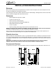
Quest Elite QLT 2000 INSTALLATION INSTRUCTIONS RECEIVING Each unit is completely tested and inspected before shipment. At time of shipment, the carrier accepts the unit and any claim for damage must be made with the carrier. Upon receiving from the carrier, please, inspect the carton for visible damage. If damage exists, have the carrier make a note on the bill of lading and file a claim with the carrier. UNPACKING • Remove staples securing carton to pallet. • Lift carton up and off of unit.
Quest Elite QLT 2000 INSTALLATION Electrical Connection 6 ft. long (1.83 m) power cord with 3-prong plug attached to dispenser. Export models are shipped with a European plug. The plug is accessible after installation ! CAUTION: Only trained and certified electrical technicians should replace the power cord or the unit should be returned to an Authorized Service Center for power cord replacement.” The replacement cord must meet all requirements of the original equipment manufacturer.
Quest Elite QLT 2000 Booster Installation Notes: Refer to the OEM manufacturers installation instructions Boosters and accumulator tanks should be fed with AMBIENT water only. To avoid condensation and premature equipment failure, do not install the water booster assembly in the refrigerated water supply circuit. To prevent pressure drops in the water supply line, use 3/8” / 9.5 mm ID supply lines only. Limit the amount of flow restrictions s.a. shut-off valves, manifolds and/or fitting.
Quest Elite QLT 2000 Flushing System To properly prime the unit with water and remove air pockets in the system, open the cabinet door and make sure the protective dust cap is in place on top of the mixing chamber. Close the door and push the “STOP” Button for a few seconds. Repeat until a steady flow of water is observed. NOTE: Water splashing may occur during this purge cycle. Figure 7. Filling the Water Bath 1. Remove the Splash Panel (2 screws next to drip tray brackets) . 2. Release filling tube. 3.
Quest Elite QLT 2000 Programming the Portion Control 1. Simultaneously, press and hold “small” and “extra large” push button switches on the Portion Control Module until the “REFILL” light in the corner of the module starts blinking. Release the switches. The blinking light indicates the programming mode is active. 2. Place the cup under the white mixing valve nozzle and push the selected size button (small, medium, large, or extra large).
Quest Elite QLT 2000 Loading With Concentrate Pouches – 6.5 Liters 1. Place the empty pouch holder on its back onto the counter. 2. Grab the pouch by the tube connector and place it vertically on the counter next to the pouch holder. Figure 11. 3. Locate the silicon tube through the slot, and slide the top of the pouch inwards. 4. Do not pull the silicone tube to guide the pouch into the pouch holder. Figure 12. 5.
Quest Elite QLT 2000 Loading with Concentrate Pouches – 3.0 & 4.5 Liters 1. Place the pouch holder on its side onto the counter.If applicable, first remove the empty pouch and discard. 2. To open, push the sides of container slightly inwards on both sides (see arrows) and simultaneously turn open the lid. Figure 17. 3. Turn the lid to face upwards or all the way down to the counter. Figure 18. 4. Locate the silicon tube through the slot, and place the pouch into the pouch holder.
Quest Elite QLT 2000 6. Open the cabinet door, open the QLT pump and slide the pouch holder onto the pouch holder shelf. 7. Locate the silicone tube into the pump and close the pump slide. Figure 21. Connecting the silicone tube onto the Mixing Chamber 1. Remove the Nozzle with the Static Mixer, remove the Mixing Chamber and place onto the drip tray 2. Position the silicone tube into the QLT pump Figure 22. 3.
Quest Elite QLT 2000 4. Connect the nipple of the mixing chamber onto the silicone tube 5. Hold the mixing chamber sideways when sliding the nipple onto the silicone tube Figure 24. 6. Slide the Mixing chamber in position and push firmly into the pump deck. ! CAUTION: Make sure that the lid of the mixing chamber is properly installed and screwed on tight. Failure doing so will cause the entire chamber to flood with drinks and eliminating the anti-splattering effect. Figure 25. 7.
Quest Elite QLT 2000 PLANNED MAINTENANCE Daily – Flushing the system 1. Set both flush switches to “Flush” position. 2. Open the cabinet door. Move both LH and RH flush switches from the “Run” position to the “Flush” position. Close the cabinet door. Figure 27. 3. Place small cold-drink cup under each dispensing nozzle. 4. Place a small, empty, cold-drink cup on the drip tray under the nozzles. Figure 28. 5. Flush nozzles. 6.
Quest Elite QLT 2000 13. Clean outside of cabinet. 14. Wipe down the outside of the cabinet and the splash panel with a cleaned towel. Place the towel in the soiled towel bucket. Figure 33. Weekly – Sanitizing Dispense Parts 1. Perform the DAILY Cleaning Procedures 2. Disconnect mixing chambers from concentrate pouch tubes and remove mixing chambers. 3. Remove the chambers by pulling it firmly toward you. NOTE:Do not open the pump while the concentrate tube is disconnected from the mixing chamber.
Quest Elite QLT 2000 14. Dispense a small portion juice to prime the mixing chambers. 15. Press the dispense button to fill a small cold-drink cup with juice. Discard the juice. Figure 39. Weekly – Check Ratio (Prodecure) 1. Turn the nozzles to the left or right ¼ turn and pull down to remove the nozzles and static mixers. Figure 40. 2. Disconnect mixing chambers from concentrate pouch tubes and remove mixing chambers. 3. Remove the mixing chambers by pulling firmly toward you. Figure 41. 4.
Quest Elite QLT 2000 8. Place the RVC onto the drip tray and the water and concentrate chambers locating under the splitter tubes Figure 45. 9. Dispense Water and Concentrate into the RVC 10. Push the Cancel/Pour button until approx. 300 ~ 350 ml of water has dispensed into the RVC water chamber. Figure 46. 11. Read the RATIO from the RVC 12. Place the RVC onto a flat surface and read both water and syrup volumes. Figure 47. 13. Calculate the Water to Concentrate Ratio. 14.
Quest Elite QLT 2000 20. Replace the mixing chambers and reconnect to concentrate pouch tubes. 21. Reinstall the parts in the juice dispenser. 22. Sanitize the syrup splitter and put aside in a safe and clean location Figure 50. Monthly - Clean the Air Condenser Filter 1. Pull the magnetic filter off the rear panel of the juice dispenser. Figure 51. 2. Clean the filter in a bucket of warm soapy water. Figure 52. 3. Place the filter on a clean, sanitized towel to allow it to air dry. Figure 53. 4.
Quest Elite QLT 2000 Semi-Annually - Clean the Water Inlet Strainer 1. Pull the AC plug from the wall outlet Figure 55. 2. Remove the right side panel from the dispenser. 3. Turn off the water supply to the dispenser. 4. Remove the access port from the “Y” shaped water inlet solenoid located on the right side of the dispenser. 5. Clean and reinstall the stainless steel water strainer. Figure 56.
Quest Elite QLT 2000 TROUBLESHOOTING GUIDE The following tables contain trouble-shooting information intended to aid an experienced service person in diagnosing operational problems that may occur. For further assistance, contact the Cornelius Customer Services department at 800-238-3600 between the hours of 7:30A.M. and 5:00P.M. Central Standard Time. You must have the model and serial number (Located on the right side of the dispenser) when calling. Symptom Probable Cause A.
Quest Elite QLT 2000 Symptom Probable Cause Remedy A. Black service switch located on the rear of A. Turn on switch. the cabinet door in OFF position. No water & no concentrate, refrigeration is working. No concentrate dispensed, water only. B. White door switch open B. Door switch must be closed in order to dispense. Check switch operation & replace if necessary. C. 6.25 amp fuse inside front electrical box blown. C. Replace with 6.25, 250VAC slow blow fuse & test. D.
Quest Elite QLT 2000 Symptom Probable Cause A. Pump motor defective. Pump inoperative Remedy A. 28VDC should be present at pump motor during dispense. If voltage is present & motor does not start, replace motor. B. No power to transformer or no 24VAC out- B. Confirm transformer has line voltage presput from transformer. ent on primary side. If no 24VAC output from secondary, replace transformer. C. Defective voltage regulator board (VRB) located inside front electrical box. C.
Quest Elite QLT 2000 WIRING DRAWING FOR QUEST ELITE QLT-2000 Figure 57. © 2013-2015, Cornelius Inc.
Quest Elite QLT 2000 Figure 58. Figure 59.
Quest Elite QLT 2000 Illustrated Parts List QLT 2000 FINAL ASSEMBLY Figure 1. Item Item Part No. Description 1 620047969 Hinge Top Cover, Quest Elite 2/4 FL 2 620047744 Merchndsr Assy Qst2 2FL 3 620054876 Side Panel LH. Quest Elite 2/4 FL 4 Tray, Black W/Texture, Quest Elite 2 620049855 Drip FL 5 620708562 Cup Rest W/LOC Quest 2 STND 8.
Quest Elite QLT 2000 Illustrated Parts List QLT 2000 DOOR ASSEMBLY REFERENCE (PUSHBUTTON & PORTION CONTROL) 10 6 16 14 8 17 7 9 5 15 4 1 13 2 3 12 Figure 2. Item Part No. Description Item Part No.
Quest Elite QLT 2000 Illustrated Parts List CABINET ASSEMBLY REFERENCE 15 14 Figure 3. Item 1 2 Part No. 620049842 Item Description Cabinet Assy QST Elite 2FL Modified Drain Part No. 6 620047970 Trim Bottom W/Insert, Quest Elite, 2FL 7 720201479 Bracket Dual Nozzle Block Quest 8 07040007 Screw Machine, #8-32 PAPH 28SS 720522100X Platform Asy Qlt Qst 2000 720506104 Fan Assembly 115/60/50 4.7 X 4.7X1.0 720506105 Fan Assembly 230/50/60 4.7 X 4.7 X1.
Quest Elite QLT 2000 Illustrated Parts List TANK COVER ASSEMBLY P/N 620047892 3 2 4 5 Figure 4. Item Publication Number: 620058442 Part No. Description 2 729011222 Kit Service Ice Probe Assy QSTE 2FL 3 720521000 Box Elec Asy Dc QST2 QLT 4 720501502 Coil, Water, QUEST 2, 2FL 5 620049563 Coil, Refrigeration QUEST Elite 2FL - 27 - © 2013-2015, Cornelius Inc.
Quest Elite QLT 2000 Illustrated Parts List REFRIGERATION FRAME ASSEMBLY QLT 2000 Figure 5. Item Item 1 3 Part No. Description 629097391 Kit Comp 115V/60HZ QST 2 FL 629097392 Kit Comp 230V/50HZ QST 2 FL 629097393 Kit Comp 220V/60HZ QST 2 FL 620048659 Adapter, 1/4”FPT x 3/8”MF 620049959- 001 11 Cord Power Straight IEC60320-C13 Family 12 620049959- 003 Cord, Service 230V 4 5 6 13 620049959- 007 Cord Serv 200V 60 HZ IEC 60906-1 Part No.
Quest Elite QLT 2000 Illustrated Parts List PLATFORM ASSEMBLY QLT P/N 720522100X Figure 6. Item Part No.
Quest Elite QLT 2000 Illustrated Parts List VALVE BLOCK ASSEMBLY P/N 45508200X Figure 7. Item Part No. Item Description Part No.
Quest Elite QLT 2000 Illustrated Parts List ELECTRICAL BOX ASSEMBLY P/N 720521000 (FOR QLT DISPENSERS ONLY) Figure 8. Item Part No. Description Item Part No. Description 1 07115001 Screw TF, #8-32 TRPH, 12 SS 7 720521500 Reg. Voltage Assembly QLT Quest 2000 2 45621 Label Pump Speed Switch 8 45432001 Rocker Switch Assembly 3 720901002 Label Wiring E-Box 9 720521201 Cover Electrical Box Quest 2000 4 45758 Label Fuse Rating 10 59328001 Fuse 6.
Quest Elite QLT 2000 Illustrated Parts List POUCH HOLDER ASSEMBLY Figure 9. Item Part Number Description 620053167 Pouch Holder 6.5 liters – Stainless Steel (for 1 x 6.5 L) 620053165 Pouch Holder 3.0 liters – Stainless Steel (for 3 + 6 L) 620053166 Pouch Holder 6.0 liters – Stainless Steel (for 3 + 6 L) 620053164 Pouch Holder 4.5 liters – Stainless Steel (for 2 x 4.
Quest Elite QLT 2000 Illustrated Parts List RECOMMENDED SPARE PARTS BASED ON 10 UNITS Qty. Qty. Part No.
Cornelius Inc. www.cornelius.