VIPER 2 FLAVOR, VIPER 3 FLAVOR & VIPER 4 FLAVOR Installation Manual Release Date: October 28, 2008 Publication Number: 621260373INS Revision Date: February 12, 2010 Revision: D Visit the IMI Cornelius web site at www.cornelius.com for all your Literature needs.
CONTACT INFORMATION The products, technical information, and instructions contained in this manual are subject to change without notice. These instructions are not intended to cover all details or variations of the equipment, nor to provide for every possible contingency in the installation, operation or maintenance of this equipment. This manual assumes that the person(s) working on the equipment have been trained and are skilled in working with electrical, plumbing, pneumatic, and mechanical equipment.
Introduction . . . . . . . . . . . . . . . . . . . . . . . . . . . . . . . . . . . . . . . . . . . . . . . . . . . . . . . . . . . . . . . . . . . . . 1 System Overview . . . . . . . . . . . . . . . . . . . . . . . . . . . . . . . . . . . . . . . . . . . . . . . . . . . . . . . . . . . . . . . 1 Introduction . . . . . . . . . . . . . . . . . . . . . . . . . . . . . . . . . . . . . . . . . . . . . . . . . . . . . . . . . . . . . . . . 1 Safety . . . . . . . . . . . . . . . . . . . . . . . . . . . . . . . . .
Events Setup Menu . . . . . . . . . . . . . . . . . . . . . . . . . . . . . . . . . . . . . . . . . . . . . . . . . . . . . . Setting Defrost Lockout . . . . . . . . . . . . . . . . . . . . . . . . . . . . . . . . . . . . . . . . . . . . . . . . Setting the Sleep and Wakeup Times . . . . . . . . . . . . . . . . . . . . . . . . . . . . . . . . . . . . . Setting Viscosity. . . . . . . . . . . . . . . . . . . . . . . . . . . . . . . . . . . . . . . . . . . . . . . . . . . . . . . . . Commissioning the Unit . .
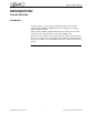
Viper Installation Manual INTRODUCTION SYSTEM OVERVIEW Introduction The Viper system is a state-of-the-art FCB/FUB machine. Viper provides improved drink availability, reliability and reduced complexity in a compact, reduced footprint machine. Viper provides the highest quality in drink appearance and consistency while keeping operation and maintenance simple and straightforward.
Viper Installation Manual SAFETY SAFETY INSTRUCTIONS ALWAYS read and follow ALL safety instructions Safety Overview Read and follow ALL SAFETY INSTRUCTIONS in this manual and any warning or caution labels on the machine (decals, labels or laminated cards). Read and understand ALL applicable OSHA (Occupational Safety and Health Administration) safety regulations before installing or operating this machine. Recognition Recognize Safety Alerts This is the safety alert symbol.
Viper Installation Manual Safety Tips • Carefully read and follow all safety messages in this manual and safety signs on the machine. • Keep safety signs in good condition and replace missing or damaged safety signs. • Learn how to operate the machine and how to use the controls properly. • Do not let anyone operate the machine without proper training. This appliance is not intended for use by very young children or infirm persons without supervision.
Viper Installation Manual SHIPPING AND STORAGE CAUTION — Before shipping, storing, or relocating the unit, syrup systems must be sanitized and all sanitizing solution must be purged from the syrup systems. All liquids must be purged from the unit after sanitizing. A freezing ambient environment will cause residual sanitizing solution or water remaining inside the unit to freeze resulting in damage to internal components.
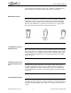
Viper Installation Manual another. Each product formulation has its own peculiarities regarding the way the product absorbs carbonation and the way it releases carbonation. BRIX Affects Overrun Sugar in carbonated drinks is like anti-freeze in water. The higher the BRIX, the greater the resistance of the product to freezing. Conversly, in products with lower BRIX, freezing takes place at higher termperatures than for high-BRIX products.
Viper Installation Manual INSTALLATION DELIVERY, INSPECTION & UNPACKING NOTE:IMI Cornelius is not responsible for damaged freight. If damage is found, you must save all packaging material and contact the freight carrier. Failure to contact the carrier within 48 hours of receipt may void your claim. 1. 4. Inspect the carton and note any damage, regardless if it appears minor.
Viper Installation Manual BACKROOM REQUIREMENTS Typically the supplies for the unit are located in a backroom adjoining the service area. Syrup, water and CO2 lines are then run from the backroom to the service area. The backroom supplies (syrup boxes, CO2, water filters and pumps) are typically installed on a rack system that sits on the floor, as shown in Figure 2. The CO2 cylinder is normally mounted against the wall.
Viper Installation Manual Power Cord Syrup, Water and CO2 Input Lines Figure 3 Electrical Requirements Refer to the nameplate to determine the power requirements before connecting electrical power to the unit. All of the power cords shall comply with safety requirements outlined in the EC Standards (EN60335-1 1 Clause 24.1) in countries where CE compliance is required. All cords must be HD 21 or HD 22. Line Voltage The recommended line voltage range for the Viper unit is 215 to 245VAC.
Viper Installation Manual Electrical Connections To connect AC power to the unit, perform the procedure in Table 2. 60Hz units are supplied with the power cord attached. Skip installation information in Table 2 and begin with the Water Supply Requirements section. Table 2 Step Action 1 Insure that power to the unit is off. DO NOT plug the power cord into the wall outlet at this time. 2 Remove the right side and rear panel from the unit. 3 Remove the cover from the electrical box.
Viper Installation Manual Water Supply Requirements NOTE: Water connections require 1/2” I.D. tubing. All hoses must reach the back of the unit plus an adequate amount of extra tubing to allow the unit to be pulled out for servicing. The Viper unit is designed as a high throughput unit. It is very important that the incoming water line is dedicated to the uint. This line should not have any other machines connected which could cause a water surge, such as coffee makers or ice machines.
Viper Installation Manual Low Pressure Bulk System requires a Secondary Regulator with a Maximum inlet pressure of 200 psi. NOTE: CO2 connections require 1/4” I.D. tubing. All hoses must reach the back of the unit plus an adequate amount of extra tubing to allow the unit to be pulled out for servicing. NOTE: Use a dedicated secondary regulator adjusted to 75 +/- 1 psig to supply the unit. CO2 Connections Use a dedicated secondary regulator, fittings and clamps to connect the CO2 line to the unit.
Viper Installation Manual Table 3 Step Action 4 Unit powers up with Do Not Drink and Out of Product lights on. 5 If the unit displays normal startup operation, proceed to “Setting Up the Control Panel” on page 13. INSTALLING THE DRIP TRAY Slide the drip tray into the two brackets protruding from the bottom of the unit until the tray contacts the two detents in the brackets. See Figure 5.
Viper Installation Manual CONTROL PANEL OVERVIEW Behind the merchandiser is the control panel which includes the LCD display, shown in Figure 6. This panel controls all the functions of the unit including defrost cycles, viscosity control, sensing of supply pressures and the incoming line voltage as well as other functions and features.
Viper Installation Manual UI 000.003 I/O 000.002 MOTOR 000.001 STATUS 000.001 SW REV Figure 8 Once the System Check State verification is complete, the display automatically displays the Barrel Status menu. This is the normal or home screen for the system when the unit is running properly. It shows the status of all barrels in the system, as shown in Figure 9.
Viper Installation Manual SELECT UNIT DATA ERROR STATUS ERROR LOG 12:51P MAR 04 BACK MAIN SETUP MAINT GO Figure 10 Use the up and down arrows on the right side of the control panel to move between the various choices on the display. When the OPTION SETUP selection is highlighted, press the GO button to access the menu. The Option Setup menu (Figure 11) is displayed.
Viper Installation Manual CLOCK SETUP TIME: DATE: 11:00 AM 01/01/00 12:51P MAR 04 BACK CLOCK DST - + Figure 12 To set the date, perform the procedure in Table 5 and refer to Figure 12. Table 5 Step Action Procedure 1 Set date Use the up and down arrows on the right side of the control panel to highlight the DATE display on the screen.
Viper Installation Manual Table 6 Step Action Procedure 6 Select SPRING WEEK Use the up and down arrows to select SPRING WEEK. 7 Set SPRING WEEK Use the + or - buttons at the bottom of the display to set the correct week. The choices are 1, 2, 3 or L. 8 Select FALL MONTH Use the up and down arrows to select FALL MONTH. 9 Set FALL MONTH Use the + or - buttons at the bottom of the display to set the correct month. 10 Select FALL WEEK Use the up and down arrows to select FALL WEEK.
Viper Installation Manual Table 7 Option Button 2 Button 3 Button 4 Button 5 Temp Format o Date Format USA EURO Time Format POS Lighting F o C 12 HR 24 HR OFF ALWAYS SLEEP #1 SYRUP TYPE FCB FCB-L FUB FUB-L #X SYRUP TYPE FCB FCB-L FUB FUB-L When all the options are set to the desired settings for the unit, press the BACK button to store these settings and return to the Select menu, shown in Figure 11.
Viper Installation Manual Light (diet), FUB is for Frozen Uncarbonated Beverages and FUB-L is for Frozen Uncarbonated Beverages - Light (diet). Each of these settings provides the proper viscosity and temperature settings for the type of syrup being used. Events Setup Menu Events setup allows the user to set sleep periods for the unit and to lock out the defrost cycle during peak busy times.
Viper Installation Manual Table 8 Step Action Procedure 12 Select DEFROST LOCK 2 Repeat Steps 2 through 11 for the DEFROST LOCK 2 time, if desired. 13 Select DEFROST LOCK 3 Repeat Steps 2 through 11 for the DEFROST LOCK 3 time, if desired.
Viper Installation Manual Table 9 Step Action Procedure 10 Set Wakeup day/time Repeat Steps 5 through 7. 11 Save the WAKEUP setting Press the BACK button at the bottom of the display to save the wakeup setting. When the sleep and wakeup settings are complete, press the BACK button to save the settings and return to the Select menu, shown in Figure 11. Setting Viscosity The viscosity maintained in the freeze barrels depends on the type of product being served.
Viper Installation Manual COMMISSIONING THE UNIT Pressurizing the CO2 System The Viper unit is designed to operate on a CO2 input pressure of 75 +/- 1 psig. If the installation location has either an independant tank and regulator or a bulk CO2 supply that feeds more than one machine, a shutoff valve and secondary regulator must be placed in the line from the bulk supply to the Viper unit to reduce the CO2 pressure at the unit to 75 +/- 1 psig.
Viper Installation Manual Pressurizing the Water System Perform the procedure in Table 13 to verify the water connection to the unit. Table 13 Step 1 2 3 4 5 6 7 8 Action Turn on the water supply to the unit. Check the system for leaks. The Do Not Drink and Out of Product lights remain on. NOTE: The H2O Out error does not clear until CO2 pressure is applied. Turn the product supply valve to the down (BRIX) position and open the valve at the end of the sample tube. Place the end of the tube in a bucket.
Viper Installation Manual Pressurizing the Syrup System Perform the procedure in Table 14 to pressurize the syrup system. Table 14 Step Action 1 Slowly turn on the CO2 regulator for the syrup BIB pumps to avoid damaging them and set them so there is 65-70 psig syrup pressure at the unit. Turn the product supply valve to the down (BRIX) position and open the valve at the end of the sample tube. Place the end of the tube in a bucket.
Viper Installation Manual Table 15 Step Action 1 2 3 Remove the drip tray by sliding it forward off the mounting brackets. Remove the splash panel behind the drip tray (if not removed). Turn product supply valve to the Down (BRIX) position for the barrel you are going to test. (See Figure 19) From the Maintenance menu (Figure 18), open the BRIX Setup menu. NOTE: Entering the BRIX Setup menu turns off all the barrels in the system. Use the up and down arrows to highlight BRIX SETUP.
Viper Installation Manual Adjusting BRIX Level If the BRIX reading is out of its proper range, the syrup level should be adjusted to bring BRIX into the proper range. NEVER change the WATER FLOW CONTROL setting to adjust BRIX. The syrup flow control adjustment valve is shown in Figure 20. Perform the procedure in Table 16. Table 16 Step Publication Number: 621260373INS Action 1 Remove the drip tray and the access panel behind it, if not already removed.
Viper Installation Manual Water Flow Control Knob (Do Not Adjust) Syrup Flow Control Knob Figure 20 FUB Product Level FCB Product Level Relief Valve Figure 21 Filling the Barrels Once the barrels have been BRIXed and purged, they may be filled with product. This is accomplished by going to the Barrel Maintenance menu and pressing the FILL button. This starts the fill process for the highlighted barrel. As the barrel fills, the barrel pressure sensor shuts off the barrel at a pressure of 28 psi.
Viper Installation Manual Security Menu The unit is shipped from the factory with security disabled. It is recommended that security be enabled when installation is complete. This is accomplished by turning security on from the System menu, as shown in Figure 22. SYSTEM # OF BARREL 2 # OF COMPRESSOR 1 SECURITY OFF 12:51P MAR 04 BACK OFF ON Figure 22 Highlight Security and press the ON button to turn on security. Press the BACK button to exit the menu and save the setting.
Viper Installation Manual TROUBLESHOOTING Table 17 Problem Probable Cause Unit will not run. A. B. Unit not plugged in Circuit breaker A. B. “Sleep” display on Barrel Status menu A. B. C. Sleep time set Clock incorrectly set No or incorrect wakeup time set A. Check programming B. Check programming C. Check programming Barrel Status OFF A. Not activated A. B. Error has shut down barrels Unit in diagnostics C. No water pressure A. B. C. © 2008-2009, IMI Cornelius Inc.
Viper Installation Manual SPECIFICATIONS Line Voltage: . . . . . . . . . . . . . . . . . . . . . . . . . . . . . . . . . . . . . . . . . . 215-245VAC Max. Current Draw (FLA): 2 Barrel Unit . . . . . . . . . . . . . . . . . . . . . . . . . . . . . . . . . . . . . . . . . . . . . . 16 amps 3 Barrel Unit . . . . . . . . . . . . . . . . . . . . . . . . . . . . . . . . . . . . . . . . . . . . . . 20 amps 4 Barrel Unit . . . . . . . . . . . . . . . . . . . . . . . . . . . . . . . . . . . . . . . . . . . . . .
IMI Cornelius Inc. www.cornelius.