CHILLER MODELS: CH1001-A Operator’s & Installation Manual Release Date: August 9, 2002 Publication Number: 620914301 Revision Date: May 6, 2010 Revision: E Visit the IMI Cornelius web site at www.cornelius.com for all your Literature needs.
CH SERIES CHILLER OPERATOR’S & INSTALLATION MANUAL The products, technical information and instructions contained in this manual are subject to change without notice. These instructions are not intended to cover all details or variations of the equipment, nor to provide for every possible contingency in the installation, operation or maintenance of this equipment.
General Information. . . . . . . . . . . . . . . . . . . . . . . . . . . . . . . . . . . . . . . . . . . . . . . . . . . . . . . . . . . . . . . 1 Introduction . . . . . . . . . . . . . . . . . . . . . . . . . . . . . . . . . . . . . . . . . . . . . . . . . . . . . . . . . . . . . . . . . . . 1 Unpacking and Inspection . . . . . . . . . . . . . . . . . . . . . . . . . . . . . . . . . . . . . . . . . . . . . . . . . . . . . . . . 1 Design Data . . . . . . . . . . . . . . . . . . . . . . . . . . . . . . . . .
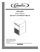
CH1001-A Chiller Operator’s & Installation Manual GENERAL INFORMATION INTRODUCTION The Cornelius ”CH” Series Recirculating Water Chiller is designed to provide an accurate, reliable, and userfriendly system for cooling a continuous flow of pure liquid and keep that liquid at a constant temperature in various closed loop or tank cooling applications. The ”CH” Series Chiller consists of an air–cooled refrigeration system housed in a sturdy sheet metal frame and cabinet.
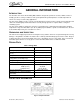
CH1001-A Chiller Operator’s & Installation Manual When servicing a Cornelius Chiller, it is important to note the information contained on the data plate located in the upper rear of the Unit. If technical assistance is needed, the phone technician will need the Serial Number of your chiller. That information is found on the Data Plate along with the model number, voltage requirement and refrigerant information.
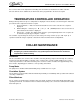
CH1001-A Chiller Operator’s & Installation Manual The data plate, located next to the junction box, includes the actual voltage, phase, and amerage of the chiller. CAUTION: On three-phase applications, it is important that the rotation of the pump, when supplied , is correct. Operating the pump in reverse for more than a few seconds will result in permanent pump damage. When the pump is operating, the shaft rotation must match the direction indicated on the pump housing.
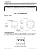
CH1001-A Chiller Operator’s & Installation Manual Control Power Switch/Light A lighted ON/OFF pushbutton switch, shown in Figure 3, is used to switch power to the 24VAC control circuit. The switch illuminates to indicate that the chiller power is present. Bypass Light (Blue) A blue light, shown in Figure 3, is used to indicate when the system is operating at a reduced capacity. The light cycles on and off in response to the temperature controller when the system temporarily requires less cooling.
CH1001-A Chiller Operator’s & Installation Manual Process water flow can be adjusted via a throttling valve and flow meter installed in the chiller outlet line. Once the flow has been established, the thermostat can be programmed to the desired set-point. TEMPERATURE CONTROLLER OPERATION During normal operation, the process temperature is displayed on the Controller, as shown in Figure 4. Follow the procedure below to adjust the Controller set point: 1.
CH1001-A Chiller Operator’s & Installation Manual FLUID RECOMMENDATIONS Cornelius chillers are designed to operate with water to provide maximum performance for temperatures of 40° F (4.4° C) to 100° F (37.8° C).
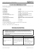
CH1001-A Chiller Operator’s & Installation Manual Trouble Pump does not operate, but Power Light is “ON”. Problem Cause Remedy A. Line to or from chiller is restricted. A. Inspect lines and remove any obstructions. B. Internal or external filter is blocked with debris. B. Remove and clean strainer, then replace. C. Pump contactor is defective. C. Replace contactor. D. Damaged pump motor or impel- D. Replace pump motor or impeller. ler.
Ice Frost Operator’s Manual Figure 5. Process Water Flow Schematic Figure 6. Refrigeration Schematic Publication Number: M620919596OPR -8- © 2004-2007, IMI Cornelius Inc.
CH1001-A Chiller Operator’s & Installation Manual Figure 7. Wiring Diagram © 2002-2010, IMI Cornelius Inc.
CH1001-A Chiller Operator’s & Installation Manual Figure 8. Cabinet Section Exploded View Table 1. Cabinet Section Table 1. Cabinet Section Item No. Part No. 1 2 3 4 620028005 620028001 620043210 620604501 Base, Pump/Tank Panel, Front Electrical Junction Box Condensing Unit 5 6 7 620028003 620028004 620604302 Panel, Side Lid, Chiller Accumulator 32357 187483000 32382 620306708 41331 61003 60686 Pump Clamp Motor Electrical Box Assy Y-Strainer TXV Filter Dryer 8 10 11 12 13 Item No.
CH1001-A Chiller Operator’s & Installation Manual Figure 9. Electrical Box Assemby, Exploded View Table 2 Item No. Part No. Name 1 620028012 Enclosure, Electric Box 2 32829R Transformer 3 31001 Safety, Low Temp 4 60501 Safety, High Pressure 5 33082 Pump/Relay 8 620305902 Compressor/Contactor 10 31407 Fuse Block © 2002-2010, IMI Cornelius Inc.
CH1001-A Chiller Operator’s & Installation Manual WARRANTY IMI Cornelius Inc. warrants that all equipment and parts are free from defects in material and workmanship under normal use and service. For a copy of the warranty applicable to your Cornelius or Wilshire product, in your country, please write, fax or telephone the IMI Cornelius office nearest you. Please provide the equipment model number, serial number and the date of purchase.
IMI Cornelius Inc. www.cornelius.