IMI CORNELIUS REMCOR INC g 500 REGENCY DRIVE g GLENDALE HEIGHTS, IL 60139--2268 Telephone (800) 551--4423 Facsimile (800) 519--4423 CHILLER (“CH” SERIES) Models: Operator’s Manual CH 1001-A CH 1501-A CH 1502-A CH 1503-A Part No. 620914301 July, 2000 Revision C Control Code A THIS DOCUMENT CONTAINS IMPORTANT INFORMATION This Manual must be read and understood before installing or operating this equipment IMI CORNELIUS INC; 1999--2000 PRINTED IN U.S.
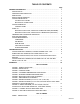
TABLE OF CONTENTS Page GENERAL INFORMATION . . . . . . . . . . . . . . . . . . . . . . . . . . . . . . . . . . . . . . . . . . . . . . . . . . 1 INTRODUCTION . . . . . . . . . . . . . . . . . . . . . . . . . . . . . . . . . . . . . . . . . . . . . . . . . . . . . . UNPACKING AND INSPECTION . . . . . . . . . . . . . . . . . . . . . . . . . . . . . . . . . . . . . . . . DESIGN DATA . . . . . . . . . . . . . . . . . . . . . . . . . . . . . . . . . . . . . . . . . . . . . . . . . . . . . . . .
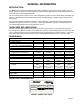
GENERAL INFORMATION INTRODUCTION The REMCOR ”CH” Series Recirculating Liquid Chiller is designed to provide an accurate, reliable, and user-friendly system for cooling a continuous flow of pure liquid and keep that liquid at a constant temperature in various closed loop or tank cooling applications. The ”CH” Series Chiller consists of an air--cooled refrigeration system housed in a sturdy sheet metal frame and cabinet.
When servicing a REMCOR Chiller, it is important to note the information contained on the data plate located in the upper rear of the Unit. If technical assistance is needed, the phone technician will need the Serial Number of your Chiller. That information is found on the Data Plate along with the model number, voltage requirement, and refrigerant information. The serial Number is also needed when replacement parts are being ordered or for warranty claims. See CHILLER WARRANTY PAGE.
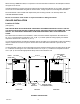
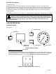
Electrical Connections (see Figure 2 and 8) All wiring must conform to the National Electric Code and any applicable local codes. The Chiller must be permanently wired by means of electrical conduit to a properly fused disconnect of proper amperage or wired to a properly rated power cord and plugged into an outlet with the appropriate disconnect and amperage rating. The electrical junction box, located on the back panel of the Chiller, includes a four terminal strip for power supply connection.
2. CONTROL POWER SWITCH/LIGHT (see Figure 3) A lighted ON/OFF push button switch is used to switch power to the 24 VAC control circuit. The switch lights up to indicate that the Chiller power is present. 3. BYPASS LIGHT (BLUE) (see Figure 3) A blue light is used to indicate when the system is operating at a reduced capacity. The light will cycle on and off in response to the Temperature Controller when the system temporarily requires less cooling. 4.
that the shaft is rotating in the direction of the arrow indicated on the pump housing. If the rotation is incorrect, reverse two of the three incoming power supply leads at the terminal strip. NOTE: Operating the pump in reverse for more than a few seconds will result in permanent pump damage. All Chillers with pumps and tank are supplied with a pressure regulating valve on the pump discharge.
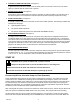
TEMPERATURE CONTROLLER OPERATION (see Figure 4) During normal operation, the process temperature will be displayed on the Controller. The following procedure should be followed to adjust the Controller set point: 1. Push and hold the “ *” button located at the bottom left corner of the Controller. The set point will be displayed. 2. While holding the “ *” button, press the desired value is displayed. (“ UP” ) or “ DOWN” button to raise or lower the set point until 3. Release the “ *” button.
Condenser On air--cooled Chillers, the CONDENSER FINS should be cleaned by blowing compressed air through the condenser from the fan side. Dirt and debris accumulate on the condenser fins over time, and this build up can severely reduce the performance of the Chiller. Cleaning of the CONDENSER COIL FINS should be done approximately every three months, depending upon cleanliness of your application.
THIS PAGE LEFT BLANK INTENTIONALLY 620914301 8
TROUBLESHOOTING WARNING: Disconnect electrical power to the Chiller to prevent personal injury before attempting any internal maintenance. Only qualified personnel should service internal components or electrical wiring. If repairs to the Chiller must be made, disconnect electrical power to the unit, then shut off the water source. TROUBLE CHILLER DOES NOT OPERATE, CONTROL POWER LIGHT “OFF” PUMP DOES NOT OPERATE, BUT POWER LIGHT IS “ON”. UNIT RUNS CONTINUOUSLY, BUT IS NOT COOLING PROCESS LIQUID ENOUGH.
TROUBLE CHILLER DOES NOT OPERATE, BUT POWER LIGHT IS “ON” AND RED SAFETY LIGHT IS “ON”. PROBABLE CAUSE REMEDY A. Unit is operating under high pressure conditions. A. Check for dirty condenser fins or obstruction of chiller air intake. Press high pressure manual reset switch. If this problem persist, contact Remcor Service Department. B. Unit is operating under low temperature conditions. B. Low or no process liquid flow. Ensure that there is adequate flow through system plumbing.
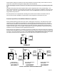
PROCESS RETURN RESERVOIR AUTO BYPASS T F PROCESS SUPPLY FLOW SWITCH (OPTIONAL) EVAPORATOR PROCESS CONTROL TEMPERATURE SENSOR T LOW TEMP SAFETY PUMP FIGURE 6. PROCESS LIQUID FLOW SCHEMATIC P HIGH PRESSURE CONTROL COMPRESSOR CONDENSER FAN EVAPORATOR SIGHT GLASS FILTER/ DRYER CONDENSER COIL TXV HOT GAS SOLENOID F FIGURE 7.
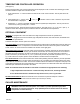
L1 L2 COND UNIT M1 M1 GRN M2 M2 PUMP GRN 230V 24V GRN HOT GAS 6 Y FUSE 1 AMP OR SOL B R 7 R 5 1 R 2 OR Y 3 Y COMPRESSOR COIL - RED INICATOR LIGHT W - WHITE INICATOR LIGHT W 6 W POWER LIGHT 2 OR 6 W T CONTROLLER POWER WIRE COLOR CODING B = BLACK BL = BLUE R = RED OR = ORANGE Y = YELLOW G = GREEN BR = BROWN V = VIOLET W = WHITE 8 2 R B LL SWITCH A AUD ALARM NOTES: 1) CONDENSER FAN IS ONLY REQUIRED ON AIR COOLED UNITS. 2) THERMAL OVERLOADS ARE BUILT INTO THE COMPRESSORS.
M1 R L1 L2 COMPRESSOR B M2 230V PUMP TRANSFMR 24V SVHG CT Y 5 VDC + - FU1 1 R 15 14 7 R FL PB 2 OR BL 5 R V M1 SSR M2 R R 12 FS 13 SSR RATING 5 FLA, 30 LRA @ 240V HI-TEMP INTERLOCK LT 9 R R 3 Y HP J 4 V M3 11 10 BL BL W 6 W 6 W 6 TR 2 W 2 OR 6 W 2 OR M3 6 W 6 5 V R LOW FLOW RELAY 1/3 H.P., 240V. 10A.
L1 L2 L3 M1 BL R G COMPRESSOR B CCH 230V 460V M2 PUMP TRANSFMR 24V + 5 V DC 15 14 PB FUI SSR 12 7 FL 1 2 R OR 5 R V 10 11 M3 BL LOW FLOW INTERLOCK LT 9 R R M1 3 HP Y LP 4 M3 V 5 V 2 W CAL OR 6 W 6 W 2 6 W W R OR 6 W 6 TR 2 LOW FLOW RELAY 1/3 HP @ 230V 10A W M2 FS 6 6 BL R 13 SSR RATING = 5 FLA, 30 LRA @240V HI TEMP INTERLOCK BL SVHG CT Y _ 6 B SSR W W 2 LLS 8 R LEGEND M1 - COMPRESSOR CONTACTOR M2 - PUMP RELAY M3 - LOW FLOW INTERLOCK
6 21 16 3 10 17 8 9 15 23 11 13 1 2 5 26 12 22 14 18 19 25 24 20 7 4 FIGURE 11.
CABINET SECTION Item No. Part No. Item No. Name Part No.
2 3 4 5 7 5 9 10 8 11 1 8 6 FIGURE 12. ELECTRICAL BOX ASS’Y EXPLODED VIEW Item No. Part No. Item No. Name Part No.
WARRANTY IMI Cornelius Inc. warrants that all equipment and parts are free from defects in material and workmanship under normal use and service. For a copy of the warranty applicable to your Cornelius, Remcor or Wilshire product, in your country, please write, fax or telephone the IMI Cornelius office nearest you. Please provide the equipment model number, serial number and the date of purchase. IMI Cornelius Offices AUSTRALIA D P.O.
THIS PAGE LEFT BLANK INTENTIONALLY 17 620914301
IMI CORNELIUS INC.