CHILLER Model CH3000 Operator’s & Installation Manual Release Date: February 14, 2011 Publication Number: 620054173OPR Revision Date: May 08, 2014 Revision: B Visit the Cornelius web site at www.cornelius.com for all your Literature needs.
The products, technical information, and instructions contained in this manual are subject to change without notice. These instructions are not intended to cover all details or variations of the equipment, nor to provide for every possible contingency in the installation, operation or maintenance of this equipment. This manual assumes that the person(s) working on the equipment have been trained and are skilled in working with electrical, plumbing, pneumatic, and mechanical equipment.
TABLE OF CONTENTS Safety Instructions. . . . . . . . . . . . . . . . . . . . . . . . . . . . . . . . . . . . . . . . . . . . . . . . . . . . . . . . . . . . . . . . . 1 Read and Follow ALL Safety Instructions . . . . . . . . . . . . . . . . . . . . . . . . . . . . . . . . . . . . . . . . . . . . . 1 Safety Overview . . . . . . . . . . . . . . . . . . . . . . . . . . . . . . . . . . . . . . . . . . . . . . . . . . . . . . . . . . . . . . 1 Recognition . . . . . . . . . . . . . . . . . . . . . . . . . . . . .
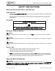
CH3000 Chiller Operator’s & Installation Manual SAFETY INSTRUCTIONS READ AND FOLLOW ALL SAFETY INSTRUCTIONS Safety Overview • Read and follow ALL SAFETY INSTRUCTIONS in this manual and any warning/caution labels on the unit (decals, labels or laminated cards). • Read and understand ALL applicable OSHA (Occupational Safety and Health Administration) safety regulations before operating this unit. Recognition Recognize Safety Alerts ! This is the safety alert symbol.
CH3000 Chiller Operator’s & Installation Manual SAFETY PRECAUTIONS This unit has been specifically designed to provide protection against personal injury. To ensure continued protection observe the following: ! WARNING: Disconnect power to the unit before servicing following all lock out/tag out procedures established by the user. Verify all of the power is off to the unit before any work is performed. Failure to disconnect the power could result in serious injury, death or equipment damage.
CH3000 Chiller Operator’s & Installation Manual GENERAL INFORMATION INTRODUCTION Cornelius CH Series, Refrigerated Recirculating Water Chillers are designed to provide a continuous flow of clean cooling water at a constant temperature and to handle a variety of closed loop and tank cooling applications. The CH Series consists of a refrigeration system with associated operating controls housed in a sturdy sheet metal cabinet.
CH3000 Chiller Operator’s & Installation Manual Figure 1. Installation Details ELECTRICAL All wiring must conform to the National Electric Code and any applicable local codes. The chiller must be PERMANENTLY wired by means of electrical conduit to a properly fused disconnect of proper amperage or wired to a properly rated power cord and plugged into an outlet with the appropriate disconnect and amperage rating.
CH3000 Chiller Operator’s & Installation Manual Failure to comply could result in serious in jury, death or damage to the equipment. Follow standard plumbing practices and local codes in making water connections. The chiller inlet and outlet connections are 3/4-inch. Flexible hoses and fittings are recommended for plumbing the system. A No.
CH3000 Chiller Operator’s & Installation Manual START UP WATER FLOW START UP Chiller with Pump It is important to check the pump rotation on the three phase units. Remove the lower side panel to expose the pump. Turn the pump power switch to the “ON” position for a few seconds. Observe the motor shaft to ensure that it is turning in the direction indicated by the arrow located on the pump housing. If the rotation is incorrect, reverse two of the three incoming power supply leads at the terminal strip.
CH3000 Chiller Operator’s & Installation Manual COOLING START UP Once flow is established and the thermostat is set to the desired set-point, turn the control power switch to “ON” (press in). All alarm indicators should be extinguished and the Chiller refrigeration system will cycle in order to maintain the established set-point.
CH3000 Chiller Operator’s & Installation Manual MAINTENANCE ! WARNING: Disconnect power to the unit before servicing. Follow all lock out/tag out procedures established by the user. Verify all power is off to the unit before performing any work. Failure to comply could result in serious injury, death or damage to the equipment. ! WARNING: The chiller requires very little normal maintenance. 1.
CH3000 Chiller Operator’s & Installation Manual TROUBLESHOOTING NOTE: Only qualified personnel should service internal components or electrical wiring. ! WARNING: If repairs are to be made to the refrigeratino system, make sure electrical power is disconnected from the unit. Trouble Chiller does not operate, Control Power light OFF. Pump does not operate. Pump Power light “OFF” Pump does not operate. Pump Power light “ON”. Chiller does not cool. Cooling light “OFF”. Chiller does not operate.
CH3000 Chiller Operator’s & Installation Manual SERVICE One servicing this chiller, it is important to note the information contained on the data plate located in the upper rear of the unit If technical assistance as needed, the phone technician will need the model and serial number of your chiller. That information is found on the data plate. The model and serial number also needed one order replacement parts. Figure 7.
CH3000 Chiller Operator’s & Installation Manual solution is used. Contact Technical Service Department for temperatures below those stated here (See Fluid Recommendations page). Low Pressure Control (LPC) This control prevents system operation in the event that the low side pressure falls below 21 PSI. If this occurs, check the following: 1. That the thermostat setpoint is set at 40° F or greater. 2. That the flow through the system is greater than 2 gallons per minute. 3.
CH3000 Chiller Operator’s & Installation Manual Figure 9. Chiller Exploded View Table 1. Chiller Section Table 1. Chiller Section Item No. 1 2 Part No. Item No. Name 3 4 5 6 7 8 9 10 11 12 13 1/2” FPT Coupling Thermaowell , Low Temp.
CH3000 Chiller Operator’s & Installation Manual Figure 10. Pump and Tank Components Table 2. Pump & Tank Components Item No. Part No. Name 1 Thermowell, Temperature Control 2 Temperature Probe 3 Tank Assembly 4 Pump 5 Pump Relief Valve ** Call the Service Dept. for proper pump identification. © 2011-2014, Cornelius Inc.
CH3000 Chiller Operator’s & Installation Manual Figure 11. Electrical Box Assembly, Exploded View Table 3 Item No. Part No. Name 1 Low Temperature Thermostat 2 Control Transformer 3 Contactor, Compressor 4 High Pressure Control 5 Low Pressure Control 6 Contactor, Pump 7 Overload Relay, 1.0 to 1.6A Overload Relay, 1.4 to 2.0A Overload Relay, 2.0 to 3.0A Overload Relay, 2.8 to 4.4A Overload Relay, 4.0 to 6.0A Publication Number: 620054173OPR - 14 - © 2011-2014, Cornelius Inc.
CH3000 Chiller Operator’s & Installation Manual WIRING DIAGRAM © 2011-2014, Cornelius Inc.
CH3000 Chiller Operator’s & Installation Manual Publication Number: 620054173OPR - 16 - © 2011-2014, Cornelius Inc.
Cornelius Inc. www.cornelius.