
Installation manual


CH3000 Chiller Operator’s & Installation Manual
COOLING START UP
Once flow is established and the thermostat is set to the desired set-point, turn the control power switch to “ON” (press
in). All alarm indicators should be extinguished and the Chiller refrigeration system will cycle in order to maintain the
established set-point.
The refrigeration system is furnished with a Hot Gas Bypass system that maintains the set-point within 1º F
temperature tolerance by cycling the Hot Gas Bypass Solenoid (Compressor, Fan Motor and Circulating pump run
continuously).
Re-check the reservoir level to ensure that it is “FULL” (if so equipped) and add water or proper fluid if necessary.
The chiller is now ready for normal operation.
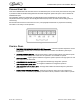
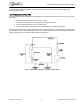
Figure 6.
CONTROL PANEL
1. TEMPERATURE INDICATOR/CONTROLLER (Thermostat) - Combines a precise temperature control
and accurate set ability with a convenient LED temperature readout that indicates system liquid
temperature.
2. CONTROL POWER SWITCH - A simple (Push Button) switch with light indicator that switches power
to the control circuit (White). This switch must be “pressed in” for the Chiller to operate.
3. COOLING LIGHT - A green light that indicates refrigeration system operation. This light cycles on and
off in response to the thermostat.
4. HIGH PRESSURE ALARM LIGHT - A red light that indicates high refrigeration pressure.
5. LOW PRESSURE ALARM LIGHT - A red light that indicates low refrigeration pressure.
6. LOW TEMPERATURE ALARM LIGHT - A red light that indicates and abnormally low system fluid
temperature.
7. PUMP POWER SWITCH (OPTIONAL) - A simple (Push Button) switch with a light indicator that
switches power to the chiller pump (White). This switch must be “pressed in” for the chiller to operate.
© 2011-2014, Cornelius Inc. - 7 - Publication Number: 620054173OPR