IMI CORNELIUS REMCOR INC 500 REGENCY DRIVE GLENDALE HEIGHTS, IL 60139–2268 Telephone (800) 551–4423 Facsimile (800) 519–4423 Operator’s Manual CHILLER (“CHILLER” SERIES) Models: CH550 and CH 551 Part No. 91272 Revised: August 9, 2002 Revision C THIS DOCUMENT CONTAINS IMPORTANT INFORMATION This Manual must be read and understood before installing or operating this equipment IMI CORNELIUS INC; 1999–2002 PRINTED IN U.S.
TABLE OF CONTENTS Page INTRODUCTION . . . . . . . . . . . . . . . . . . . . . . . . . . . . . . . . . . . . . . . . . . . . . . . . . . . . . . . . . . . 1 SPECIFICATIONS . . . . . . . . . . . . . . . . . . . . . . . . . . . . . . . . . . . . . . . . . . . . . . . . . . . . . . . . . 1 INSTALLATION INSTRUCTIONS . . . . . . . . . . . . . . . . . . . . . . . . . . . . . . . . . . . . . . . . . . . . 2 LOCATION . . . . . . . . . . . . . . . . . . . . . . . . . . . . . . . . . . . . . . . . . . . . . . .
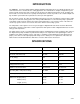
INTRODUCTION The REMCOR “CH” Series Water Chillers (Models CH550–A and CH551–A) are specifically designed to cool clean water before it is circulated to the cooling application. The Unit includes a complete refrigeration system and associated controls housed in a sturdy sheet metal enclosure with perforated panels for air circulation.
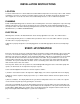
INSTALLATION INSTRUCTIONS LOCATION Locate the chiller indoors in a well ventilated area with ambient temperatures in the range of 65° to 100° F. Allow a minimum of six inches of clearance around the chiller for proper air circulation. Avoid hot air discharge from other equipment or enclosed areas where heat could build up and cause a rise in ambient temperature. PLUMBING Follow standard plumbing practices and local codes in making water connections.
When the flow rate to the process is critical, a flow meter and valve should be installed in the line in order to obtain the proper flow rate. On Units with optional bypass valve, the aforementioned valve can be omitted and the flow can be adjusted with this valve. Turning the valve clockwise increases the flow to the process whereas turning the valve counterclockwise decrease the flow to the process. Once these start–up procedures are complete, the chiller is ready for standard operation.
3. Remove the screw securing the mounting bracket to the back of the thermostat. 4. Remove the thermostat from the front panel. 5. Install the new thermostat in the front panel and secure it with the mounting bracket. 6. Reconnect the wires at back of the thermostat. 7. Install the wrapper. REPLACING ELECTRONIC DIFFERENTIAL THERMOSTAT 1. Remove the wrapper as specified in REMOVING WRAPPER. 2. Remove the two screws securing the thermostat cover and remove the cover. 3.
FLUID RECOMMENDATION Remcor Chillers are designed to operate with water to provide maximum performance for temperatures of 40 F–100 F.
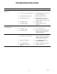
TROUBLESHOOTING GUIDE Trouble CHILLER DOES NOT OPERATE NO CIRCULATION OF CHILLED WATER INADEQUATE COOLING Probable Cause Remedy A. No power. A. Check fuse or circuit breaker. B. Loose or poor wire connection. B. Check wiring. Correct for loose or poor wire connection. C. Inoperable ON–OFF switch. C. Replace ON–OFF switch. D. Overload device open. D. Allow compressor to cool, then install new overload device; replace compressor if necessary. E. Inoperable relay. E. Replace relay. F.
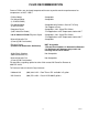
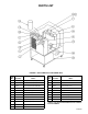
PARTS LIST FIGURE 1. CH550 AND CH551 EXPLODED VIEW Item No. 1 Part No. Item No. Name Part No. Name 31934 Switch, Illuminated (CH550) 10 61058 TXV 31935 Switch, Illuminated (CH551) 11 60514 Sight Glass 2 32386 Thermostat, Eliwell No.
WARRANTY IMI Cornelius Inc. warrants that all equipment and parts are free from defects in material and workmanship under normal use and service. For a copy of the warranty applicable to your Cornelius, Remcor or Wilshire product, in your country, please write, fax or telephone the IMI Cornelius office nearest you. Please provide the equipment model number, serial number and the date of purchase. IMI Cornelius Offices AUSTRALIA P.O.
CORPORATE HEADQUARTERS: Remcor Incorporated 500 Regency Drive Glendale Heights, IL 60139