IMI CORNELIUS INC g One Cornelius Place g Anoka, MN 55303-6234 Telephone (800) 238-3600 Facsimile (763) 422-3246 Installation/Owner’s Manual ICE MAKER (WM600 AND CM600) IMPORTANT: TO THE INSTALLER. It is the responsibility of the Installer to ensure that the water supply to the Ice Maker is provided with protection against backflow by an air gap as defined in ANSI/ASME A112. 1.2-1979; or an approved vacuum breaker or other such method as proved effective by test.
TABLE OF CONTENTS Page SPECIIFICATIONS . . . . . . . . . . . . . . . . . . . . . . . . . . . . . . . . . . . . . . . . . . . . . . . . . . . . . . . . . 3 DESCRIPTION . . . . . . . . . . . . . . . . . . . . . . . . . . . . . . . . . . . . . . . . . . . . . . . . . . . . . . . . . . . . 3 INSTALLATION INSTRUCTIONS . . . . . . . . . . . . . . . . . . . . . . . . . . . . . . . . . . . . . . . . . . . . 3 REMOVE ICE MAKER FROM CARTON: . . . . . . . . . . . . . . . . . . . . . . . . . . . . . . . . .
TABLE OF CONTENTS (cont’d) Page ELECTRICAL CHECKOUT . . . . . . . . . . . . . . . . . . . . . . . . . . . . . . . . . . . . . . . . . . . . . . 16 OVERLOAD CHECK . . . . . . . . . . . . . . . . . . . . . . . . . . . . . . . . . . . . . . . . . . . . . . . . . . . 16 COMPRESSOR CHECK . . . . . . . . . . . . . . . . . . . . . . . . . . . . . . . . . . . . . . . . . . . . . . . . 16 CAPACITOR CHECK . . . . . . . . . . . . . . . . . . . . . . . . . . . . . . . . . . . . . . . . . . . . . . . . . . .
SAFETY INFORMATION Recognize Safety Information This is the safety-alert symbol. When you see this symbol on our machine or in this manual, be alert to the potentially of personal injury. Follow recommended precautions and safe operating practices. Understand Signal Words A signal word - DANGER, WARNING, OR CAUTION is used with the safety-alert symbol. DANGER identifies the most serious hazards. Safety signs with signal word DANGER or WARNING are typically near specific hazards.
THIS PAGE LEFT BLANK INTENTIONALLY 630460082 2
SPECIIFICATIONS Model WM (Wall Model) 600 and CM (Counter Model) 600 Compressor 3/4 H.P. (R404 Refrigerant) Voltage 115 VAC, 60 Hz, Single Phase Current Draw 16 Amps Circuit Breaker or Fuse Size 20 Amp Maximum Time Delay DESCRIPTION Models WM600 and CM600 Ice Makers are self-contained wall mount and counter style Units which automatically make hard compressed-style ice and store it in a sealed hopper for sanitary dispensing.
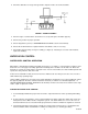
3. Apply a continuous bead of NSF listed silastic sealant (Dow 732 or equal) approximately 1/4–inch inside of the Unit outline dimensions. Then, position the Unit on the counter within the outline dimensions. All excess sealant must be wiped away immediately. IMPORTANT: The WM600 with a full ice storage hopper weighs 450 pounds. Make sure that the mounting surface is adequately reinforced to support this weight. The mounting hole dimensions for the brackets are shown in Figure 1A.
INITIAL START UP, CHECKS AND ADJUSTMENT INSTRUCTIONS NOTE: Do not start the Unit before completing the previous Installation steps. Turn on the water supply and main power switch (located on top of the electrical box). NOTE: If the Unit will not start, be sure the water reservoir is full. The low water safety control must be properly adjusted to start and shut down the Unit. If the water level drops below the bottom of the reservoir, the Unit must shut down.
GUIDE TO SERVICE IMPORTANT: Prventive maintenance can increase the trouble-free life of your Ice Maker. Failure to perform preventive maintenance could void your equipment warranty. ICE MAKER CLEANING AND SANITIZING PROCEDURES IMPORTANT: Do not use any of the ice made during cleaning operations. Clean and sanitize ice storage area when cleaning Ice Maker. 1. Turn Ice Maker off. 2. Shut off water supply. 3. Remove ice from storage bin. 4. Mix approved cleaner (2 gallons as directed).
2. Check the drain tubes for clogs and ”aged” tubes. Replace if tubes are stained or brittle. FIGURE 2. AUGER ASSEMBLY 3. Check for signs of condensation. Clean where necessary and replace insulation properly. 4. Check safety circuits for proper operation. 5. Check refrigeration system (see REFRIGERATION SYSTEMS section of this manual). 6. Check Unit for abnormal noise. Tighten machine and cabinet screws, if necessary. 7. Check white upper bearings on auger assembly (see Figure 2).
TO REPLACE WATER LEVEL CONTROL 1. Shut off the water supply. Shut off the main power switch or unplug the Ice Maker from electrical outlet. 2. Remove flexible tubing from bottom of the water level control, then drain water from the water level control and evaporator. 3. Remove flexible tubing at bottom of the water level bowl connected to the overflow. 4. Hold water inlet fitting with proper tool to prevent it from rotating when disconnecting the water inlet. 5.
REFRIGERATION SYSTEMS REFRIGERATION SYSTEM ADJUSTMENTS A complete understanding of the Ice Maker and the hermetic refrigeration system is necessary before any adjustments are made. The refrigeration technician must use high and low side pressure readings, water and air temperatures, plus general conditions of cleanliness to assess the refrigeration system status when making any adjustments.
TEMPERATURE/PRESSURE CHART + 10 LB REFRIGERANT TYPE R404A DISCHARGE PRESSURE WATER TEMPERATURE AIR TEMPERATURE 40 65 90 50– 174 177 180 60– 202 205 208 70– 230 233 236 80– 265 269 272 90– 300 304 307 100– 328 334 340 NOTE: The thermostatic expansion valve is non-adjustable on all models CONDENSER MODULATING VALVE (Water Cooled Only) The reason for using a water modulating valve is to supply the correct amount of water to the condenser to maintain the proper operating pressur
NOTE: Cold water will absorb more heat faster than warm water. The water flow will therefore automatically increase as inlet temperature increases. CONDENSER MODULATING VALVE REMOVAL 1. Disconnect power to unit, shut off water supply to condenser, then reclaim refrigerant from system. 2. Remove inlet water line from Condenser modulating Valve. Also remove tube from refrigerant high side line. 3. Remove Condenser Modulating Valve and bracket from unit. 4. Remove valve from bracket. 5.
THIS PAGE LEFT BLANK INTENTIONALLY 630460082 12
TROUBLESHOOTING IMPORTANT: Only qualified personnel should service internal components or electrical wiring. TROUBLESHOOTING GEAR MOTORS Basically, Gear motor problems can be narrowed down to three areas of checkout. THE GEARMOTOR WILL NOT RUN 1. No voltage to the transmission terminals – check external circuit. 2. Low voltage – check voltage supply. 3. Problems in the gear motor electrical circuit. See Figure 4 THE GEARMOTOR STARTS BUTS TRIPS REPEATEDLY ON THE OVERLOAD PROTECTOR 1.
If no continuity on start or run winding test, replace stator. If continuity on grounded motor test, replace stator. INSTALLATION AND SHAFT SEAL REPLACEMENT (See Figure 5) 1. Place shaft seal locator seat over gear motor output shaft, embossed side down, and push down until shaft seal seat rests flush on top of gear motor. 2. Place rubber coated ceramic seal (important: ceramic face up) over output shaft and push down until seal rests on top of the shaft seal seat.
AUGER & EXTRUDING HEAD REMOVAL FIGURE 8. UPPER NUT AND BEARING The upper bearings located on top of the auger is used to absorb the force between the auger and extruding head. The bearings are 3/32” thick. When they wear below 1/16” they should be replaced. Bearings to be inspected for wear during quarterly maintenance. See Figure 8. TO REPLACE BEARINGS 1. Dispense all ice from unit. 2. Disconnect unit from electrical power. 3. Remove panels. 4. Unplug Dispense Motor and Ice Level Switch. 5.
C. Voltage – The voltage should be within 10% of the rated nameplate voltage. D. High compressor amperage draw, it should never exceed 120% of the rated nameplate amperage. See Electrical Checkout Instructions. 3. THE COMPRESSOR RUNS BUT WILL NOT REFRIGERATE A. Check the compressor suction and discharge pressures. See TEMPERATURE/PRESSURE CHART. ELECTRICAL CHECKOUT FIGURE 9. ELECTRICAL BOX 1. Be sure the unit is disconnected from the power source. Remove the compressor electrical box cover.
10. Check or replace run capacitor (if supplied) check or shorted capacitor or either terminal grounded to case. SAFETY CONTROLS FIGURE 10. GEAR MOTOR THERMAL OVERLOAD Your Icemaker unit has several safety and control devices incorporated into its design. WARNING: None of the below described devices should ever be ”bypassed” to allow the unit to function. The safety and control system shut–off devices are: 1. Low water shut off reed switch located in icemaker float assembly. (Automatic reset type). 2.
GUIDE TO GOOD ICE CUSTOMER COMMENTS It runs but the ice is too soft. The icemaker is not producing enought ice. The ice is too wet. CHECK ICEMAKER LOCATION CONDITIONS FIRST Under compression Proper air flow for condensing system Location too close to high temp units such as coffee urns, deepfryers, grills etc. Supply water conditions. Water too warm (above 90_F) CHECK ICEMAKER Use gages for checking suction and head pressures. See manual for correct reading and conditions.
TROUBLESHOOTING CHART – ICEMAKER NOT OPERATING ICEMAKER RUNS BUT DOES NOT MAKE ICE NO POWER LOW WATER SAFTEY SWITCH OPEN –Check bin switch –Check to see if ice control plate moves freely Condenser fan runiing but compressor not running –Check electrical wiring in control box for loose connections –Check for failed service switch or relay –Check power to machine –Check line voltage –Check compressor winding & components –Check that wateris turned on –Check for restriction in water line –Check incoming
630460082 20 FIGURE 12.
67 66 47 19 20 18 21 17 58 1 61 2 59 69 70 64 29 30 28 27 22 59 67 68 26 23 58 60 25 71 59 24 21 630460082
37 38 39 36 33 40 82 85 74 35 51 34 84 83 72 88 86 81 89 41 76 52 87 73 59 32 49 57 91 90 95 92 94 93 45 75 44 43 14 2 42 48 14 1 630460082 50 22
WM600 AND CM600 ICEMAKER Item No. Part No. Item No. Name Part No.
WM600 AND CM600 ICEMAKER Item No. Part No. Item No. Name Part No.
15 14 16 11 10 9 8 7 12 4 3 5 6 1 2 FIGURE 13. FRONT END ASSEMBLY EXPLODED VIEW AND PARTS LIST Item No. 1 Part No. Item No. Name Part No.
FIGURE 14.
WARRANTY IMI Cornelius Inc. warrants that all equipment and parts are free from defects in material and workmanship under normal use and service. For a copy of the warranty applicable to your Cornelius, Remcor or Wilshire product, in your country, please write, fax or telephone the IMI Cornelius office nearest you. Please provide the equipment model number, serial number and the date of purchase. IMI Cornelius Offices AUSTRALIA D P.O.
IMI CORNELIUS INC.