Installation Guide Model 230 Wet/Wet Differential Pressure Transducer 1-800-257-3872 Toll Free 1-978-264-0292 Fax www.setra.
Table of Contents 1.0 General Information.......................................... 3 2.0 Mechanical Insallations.................................. 3 2.1 Media Compatibility................................................ 3 2.2 Environment.............................................................. 3 2.3 Pressure Fittings....................................................... 3 2.4 Moisture Precaustions............................................. 3 2.5 Mounting...........................................
Setra Model 230 Wet/Wet Differential Pressure Transducer 1.0 GENERAL INFORMATION Every Model 230 has been tested and calibrated before shipment. Setra Systems 230 pressure transducers sense differential pressure and convert this difference in pressure to a proportional high level analog output. The 230 is supplied with either a 0 to 5 VDC or 0 to 10 VDC output or current output of 4 to 20 mA. 2.0 MECHANICAL INSTALLATION 2.
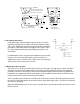
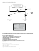
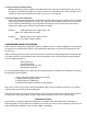
Top View Transducer Mounting Holes (screws provided: mounts to bottom of 230 transducer) 0.875 22 f f 3.00 76 2.50 0.43 11 Conduit Opening 64 0.52 13 Notched for clamp mounting 0.88 22 1.30 33 0.156 .096 f f Front View 1.50 38 1.63 41 1.63 41 in. mm 2.6 Installation Procedures If the Model 230 is supplied with an optional 3-valve or 5 valve manifold assembly, refer to Section 2.8 and 2.9. Optional 3-Valve and 5-Valve Manifold Assembly Procedure, for further installation procedures.
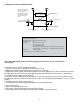
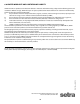
2.8 Optional 3-Valve Manifold Procedure Model 230 Differential Pressure Transducer V1 SHUNT VALVE SHUT OFF VALVE V2 V2 High Process Connection 1/4” NPT Low Process Connection 1/4” NPT 3-Valve Manifold Description Manifold Block Brass Valves (3) V1 for connection to ±port V2 for connection to -port V3 for equalizing pressure Valve Type 90 Degree On/Off Process Connection 1/4 ”-18 NPT Internal Thread The 3-Valve Manifold Assembly is normally shipped with valves V1 and V2 closed and V3 open.
2.9 Optional 5-Valve Assembly Procedure Note: V6 and V7 bleed valves are not required when used with a Setra Model 230. Use the bleed screws on Model 230 to bleed the lines of air. V6 V7 Model 230 Differential Pressure Transducer V3 V4 High Process/Commission 1/4”NPT Connection V1 SHUNT VALVE V5 Low Process/Commission V2 SHUT OFF VALVES Low Process Connection 1/4”NPT High Process Connection 5-Valve Manifold Description (Order as Pressure Code Fitting “5V” See Table below.
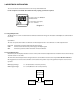
3.0 ELECTRICAL INSTALLATION To access electrical connections remove cover on top of the Model 230 For CE compliance a shielded cable with both ends properly grounded is required. For voltage output, use COM,OUT and EXC terminals For current (4-20 mA) output, use + and - terminals Diagram 1 3.1 Voltage Output Units The Model 230 is a 3-wire circuit with three terminals available for wiring. The -Excitation and -Output are commoned on the circuit.
4.0 CALIBRATION The 230 transducer is factory calibrated and should require no field adjustment. Whenever possible, any zero and/or span offsets should be corrected by software adjustment in the user’s control system. However, zero and span adjustments are made by removing the cover on the top of the 230 and the 6-32 seal screws in the plastic terminal block. Be sure to reinstall seal screws after zero and/or span adjustments.
4.3 Current Output Zero Adjustment While monitoring the current output, and with both pressure ports open to atmosphere, the zero may be adjusted. For unidirectional pressure ranges, turn the zero adjustment screw until a reading of 4 mA (±.08 mA) is achieved. For bidirectional ranges, set zero to 12 mA (±.08 mA). 4.4 Current Output Span Adjustment Span or full scale output adjustments should only be performed by using an accurate pressure standard (electronic manometer, digital pressure gage, etc.
6.