
Installation manual


Viper Installation Manual
Publication Number: 621360041TBINS - 10 - © 2010-2012, IMI Cornelius Inc.
Water Supply Requirements
NOTE: Water connections require 1/2” I.D. tubing. All hoses must
reach the back of the unit plus an adequate amount of extra tubing
to allow the unit to be pulled out for servicing.
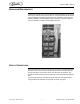
The Viper unit is designed as a high throughput unit. It is very important that the
incoming water line is dedicated to the unit. This line should not have any other
machines connected which could cause a water surge, such as coffee makers or
ice machines.
!
IMPORTANT:
The water supply should be consistent with proper water quality standards
(neutral pH of 7.0 to 8.0), and should not be connected to a water softener. Drink
quality may be affected by poor water conditions. Water connections should be
sized, installed and maintained according to federal, state and local laws.
NOTE: Size, install, and maintain the water pipe, connections, and
fixtures directly connected to a potable water supply in
accordance with Federal, State, and Local codes. It is the
installer’s responsibility to ensure that the potable water supply is
equipped with protection against backflow. This protection can be
an air gap as defined by ANSI/ASME A112.1.2-1979 or by an
approved vacuum breaker or other approved method. If the flowing
water pressure at the back of the unit is less than the specified 25
psi and 100 GPH flowrate (per 2 barrels) a water pressure booster
is required. It is recommended that a water shutoff valve and water
filter be installed in the water supply line.
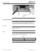
Water Connections
Use the appropriate fittings and clamps to connect the water line to the unit. Run
the tubing for the water (1/2 in. ID, Min.) from the water source in the backroom
to the unit and make all appropriate connections. Do not turn on the water
supply to the unit.
CO2 Requirements
!
WARNING:
CO2 displaces oxygen. Persons exposed to high concentrations of CO2 will
experience tremors, followed by loss of consciousness and death. It is very
important to prevent CO
2 leaks, especially in small unventilated areas. If a CO2
leak occurs ventilate the area before fixing the leak.
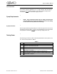
NOTE: There are two CO
2 delivery systems available: High
Pressure Cylinder; Low Pressure Bulk System.
High pressure Cylinder requires a Primary Regulator with a
minimum inlet pressure of 500 psi.
Low Pressure Bulk System requires a Secondary Regulator with a
Maximum inlet pressure of 200 psi.
NOTE: CO
2 connections require 1/4” I.D. tubing. All hoses must
reach the back of the unit plus an adequate amount of extra tubing
to allow the unit to be pulled out for servicing.
NOTE: Use a dedicated secondary regulator adjusted to 75 +/- 1
psig to supply the unit.