® ICE FROST Post-Mix and Pre-Mix Installation, Service, and Operator’s Manual Release Date: April 19, 2004 Publication Number: M620919596OPR Revision Date: October 19, 2006 Revision: C Visit the IMI Cornelius web site at www.cornelius.com for all your Literature needs.
ICE FROST POST-MIX AND PRE-MIX INSTALLATION, SERVICE, AND OPERATOR’S MANUAL The products, technical information, and instructions contained in this manual are subject to change without notice. These instructions are not intended to cover all details or variations of the equipment, nor to provide for every possible contingency in the installation, operation or maintenance of this equipment.
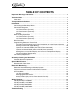
TABLE OF CONTENTS Important Warnings and Advice . . . . . . . . . . . . . . . . . . . . . . . . . . . . . . . . . . . . . . . . . 1 Technical Data . . . . . . . . . . . . . . . . . . . . . . . . . . . . . . . . . . . . . . . . . . . . . . . . . . . . . . . . 1 Plate data . . . . . . . . . . . . . . . . . . . . . . . . . . . . . . . . . . . . . . . . . . . . . . . . . . . . . . . . . 1 Transportation Indications . . . . . . . . . . . . . . . . . . . . . . . . . . . . . . . . . . . . . . . . . . . . . .
Ice Frost Operator’s Manual IMPORTANT WARNINGS AND ADVICE This instruction manual represents an integral part of the equipment and must be kept readily available for use. Read the warnings contained herein carefully before installing and using this equipment.
Ice Frost Operator’s Manual INSTALLATION 1. 2. Remove the equipment from the packing, then slide it off upwards (see FIGURE 1). Checking the machine identification after removing the packing, you must check that the equipment you have received is exactly as you ordered, making sure the specifications indicated on the invoice or the delivery note are identical to those on the data plate. FIGURE 1 3.
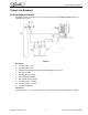
Ice Frost Operator’s Manual CONNECTION DIAGRAMS Ice Frost Generic (Pre-mix) The diagram shows the sequence for the connection between the ICE FROST GENERIC PRE to an existing pre-mix system. FIGURE 3 Description: 1. Pre-mix product 1 inlet. 2. Pre-mix product 2 inlet. 4. Inlet for CO2 (coming from the pressure reducing valve, 12 psi). 5. CO2 gas cylinder. 6. 7. Operating pressure gauge. 8. 9. 10. 11. Gas cylinder pressure gauge. Pre-mix product 1 container. Pre-mix product 2 container.
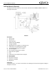
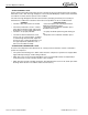
Ice Frost Operator’s Manual Ice Frost Generic (Post-mix) The diagram shows the sequence for the connection between the ICE FROST GENERIC POST to an existing post-mix system. FIGURE 4 Description: 1. Syrup 1 inlet. 2. Syrup 2 inlet. 3. Soda water inlet. 4. Inlet for CO2 45 to 60 psi. 5. CO2 gas cylinder. 6. 7. 8. 9. 10. 11. 12. 13. 14. 15. 16. 17. 18. Operating pressure regulator for carbonation unit. Carbonation unit operating pressure gauge. Unit and BIB operating pressure gauges. Pressure regulator.
Ice Frost Operator’s Manual Alarms Safety Probe Alarms (only for ICE FROST GENERIC Pre-mix) You will remember that the monitoring of the safety probes’ conditions (satisfied/ not satisfied) is only active during the bowl loading phase. It follows, then, that a lack of liquid in the tanks during the nonloading phases will not be signalled.
Ice Frost Operator’s Manual “FILTER CLEANING” Alarm A filter cleaning alarm will activate when the unit is running hot due to insufficient internal air circulation. When this occurs a “Filtr” message will appear on the touch pad LED display readout and an intermittent tone will also sound to alert the operator of this condition. The “Filtr” message will appear when the alarm activates (a beeping sound every 4-5 seconds).
Ice Frost Operator’s Manual BOWL LOADING OPERATIONS Ice Frost Generic (Pre-mix) WARNING: If the unit runs out of product and is turned off and turned back on without a new (full) product tank installed the sensor will look for product for 4 minutes. During this 4 minute period CO2 will be purged from the bowl. • Switch the machine’s main switch to the ON position (1). • Put the switch (A) into the ON position (1) see FIGURE 5, switch A. Controls the flow of the product in the bowls.
Ice Frost Operator’s Manual BRIX PROCEDURE This will be a two step process. First to adjust the water flow rate by adjusting the water flow control and second to obtain the proper Brix by adjusting the syrup flow control. 1. Rotate the valve assembly 90 degrees and slide to the outside of the machine. Tighten the 8mm nut using a socket wrench (E1), see FIGURE 7. 2. Checking and adjusting the water flow is most easily done by first disconnecting the syrup bib. 3.
Ice Frost Operator’s Manual PROGRAMMING ELECTRONIC TOUCH PAD To lower the control cover, use a coin or other object to turn the keyless lock to the horizontal position, in order to access the operating panel (controls are located on the right side of the unit). Auger ON/OFF Button Main Power Switch • Turns unit ON. Fo o • Selects 12/24 time clock or /C temperature display when turned ON while simultaneously depressing the auger button.
Ice Frost Operator’s Manual Setting COLD Timer (Night Setting) 1. 2. 3. Turn the power switch ON. Make sure the “AUTO TIMER” is OFF (light on button is not lit). Press the left hand “Auger ON/OFF” button ON. Press and hold the “PRESS TO SELECT FUNCTION” button until you hear a long beep and the LED, “Cold” and the “AUTO TIMER” clock light begins to blink. 4. Press the “AUTO TIMER” clock button to set the unit to COLD mode and then press the “PRESS TO SELECT FUNCTION” button to save the setting. 5.
Ice Frost Operator’s Manual Viewing the Bowl Temperature 1. 2. Turn ON the auger on the side that you want to display the bowl temperature (press the “AGER ON/ OFF” button). Press the “PRESS TO SELECT FUNCTION” button until the “Cold” LED is lit. The display will now show the current bowl temperature in either oF or oC as applicable. CONSISTENCY ADJUSTMENT 1. To dispense the product, place the cup beneath the dispensing valve (Q) and pull the lever (R) very gently (FIGURE 10). 2.
Ice Frost Operator’s Manual QUARTERLY CLEANING AND SANITATION POST MIX SYSTEMS OPERATIONS ATTENTION: The cleaning operations must be performed with the machine disconnected from the power supply. 1. 2. 3. Empty the bowl of any remaining product and switch off the main switch “M”. Remove the cover (B) - FIGURE 27. Extract the quick couplings (C2) / (F2) - (FIGURE 12, FIGURE 13, and FIGURE 14). Pre-mix version Post-mix version FIGURE 12 FIGURE 13 FIGURE 14 4. 5.
Ice Frost Operator’s Manual 6. Slide the locking bar (Z) - FIGURE 16 - outwards so that the bowls are fully released. Unlock relief valve on the bowl lid cap and remove (FIGURE 17). 7. Unscrew the knobs (A1) so the bowls can be lowered slightly, open the tap to remove any remaining liquids and then extract it from its seating, pulling it outwards (FIGURE 17). FIGURE 16 Bowl Lid Cap FIGURE 17 8.
Ice Frost Operator’s Manual 11. Wash the bowl and cover carefully with water and mild detergent, rinse them well, and replace them, making sure the sealing strip (E1) is positioned correctly between the cover and the bowl. To guarantee the seal, the rounded part of the said sealing strip (as shown in FIGURE 21) must be facing the cover. FIGURE 21 12.
Ice Frost Operator’s Manual 17. Replace the tap, remembering to smear both is seating in the bowl and the seals (J) with Food Grade Lubricant (FIGURE 25). FIGURE 25 18. Remove the drip tray (L1) by rotating it slightly and pulling it outwards (FIGURE 26). Wash all the parts carefully and reassemble it by following the prior operations, remembering to re-insert the condensation discharge pipe (M1) in its seating. FIGURE 26 © 2004-2006, IMI Cornelius Inc.
Ice Frost Operator’s Manual SPECIAL MAINTENANCE ATTENTION: To guarantee peak cooling system performance level, the routine cleaning of the condenser filter is essential. As explained earlier, an audible signal accompanied by the word FILT appearing on the control panel display, will warn the operator when the filter is clogged and so must be cleaned before the machine comes to an automatic stop. • Disconnect the machine from the power supply; • Unscrew the nut (C in FIGURE 27).
Ice Frost Operator’s Manual ELECTRONIC MONITORING ELECTRONIC BOWL MONITORING AND SAFETY SYSTEM The diagram shows the electronic pressures and levels management system: 1. 2. 3. 4. 5. Safety valve. Monitoring card for maximum limit exceeded probes. Bowl 1 overpressure discharge relief valve solenoids. Bowl 2 overpressure discharge relief valve solenoids. 6 CO2 inlet solenoid valve. 5 6. 7. Pressure and levels monitoring card. CO2 pressure switch.
Ice Frost Operator’s Manual OFF CONDITION In this condition, the electronic control is not connected to the power supply. To connect the ECB to the power supply, the main system switch must be put in the ON position.
Ice Frost Operator’s Manual Managing the Bowl Levels When one of the two level probes fails to detect the presence of liquid in the bowl, the Fill solenoid valve is activated to refill the correct level.
Ice Frost Operator’s Manual NOTE 1: the same intervention methods are applied when the safety probe is uncovered after the solenoid valve has been activated. NOTE 2: the 3-second software filter activated when it detects the safety probe is uncovered and the relevant signal have been introduced to prevent the probe recognizing the “tank-bowl” conduit as “empty” when there is residual gas in it.
Ice Frost Operator’s Manual WIRING DIAGRAM VFCB (PRE-MIX) 115V/60HZ FIGURE 36 © 2004-2006, IMI Cornelius Inc.
Ice Frost Operator’s Manual VFCB (POST-MIX) 115V/60HZ FIGURE 37 Publication Number: M620919596OPR - 22 - © 2004-2006, IMI Cornelius Inc.
Ice Frost Operator’s Manual VFCB (PRE-MIX) 230V/50HZ FIGURE 38 © 2004-2006, IMI Cornelius Inc.
Ice Frost Operator’s Manual VFCB (POST-MIX) 230V/50HZ FIGURE 39 Publication Number: M620919596OPR - 24 - © 2004-2006, IMI Cornelius Inc.
Ice Frost Operator’s Manual TROUBLESHOOTING NOTE: The following procedures must be performed by a qualified service technician.
Ice Frost Operator’s Manual Problem The machine over-freezes making the auger movement slow or stopped Possible Cause • The product Brix/ratio is too low • The screw setting for the product • The limit switch arm is bent away from the gearmotor and prevents contact • The level of the product in the bowl is too low, exposing the auger • The compressor PC board contacts don’t open The main power switch is “On”. The unit is not running.
Ice Frost Operator’s Manual Problem Cap is leaking Bowl not refilling Bowl is overfilling CO2 leaking from back of unit Possible Cause Solution • The nut is loose • Out of syrup • Tighten the nut • Replace • Out of CO2 • Replace • Valves are shut off or blocked • Open • Foam covering probes • Wait • Fill Switch in off position • Turn on • Defective syrup pressure switch • Replace • Defective CO2 shut off • Replace • Bad Pressure and Levels Card • Proper function of bowl over pressure disc
IMI Cornelius Inc. www.cornelius.