ICE FROST MANUAL 2.2 INSTRUCTION MANUAL Code Nr. : IMI I F M 2.
Dear Client, we would like to congratulate you for having chosen a high quality product which will surely meet all your expectations. While thanking you for the preference you have given us, we invite you to carefully read the following instruction manual before operating your ICE FROST MANUAL 2.2 slush machine.
INDEX 1 2 3 IMPORTANT WARNINGS AND SUGGESTIONS page 3 TECHNICAL CHARACTERISTICS page 3 2.1 page 3 Specification plate INSTRUCTIONS FOR MACHINE TRANSPORT page 3 4 INSTALLATION page 4 5 CONNECTION TO POWER SUPPLY MAINS page 5 6 CONNECTION DIAGRAM page 6 7 REFILLING OPERATIONS page 7 8 START-UP PROCEDURES page 8 8.
1 - IMPORTANT WARNINGS AND SUGGESTIONS The present instruction manual is an important part of the ICE FROST MANUAL 2.2 slush machine and must be kept for any future consultation. Carefully read the warnings contained in this instruction manual before installing and operating the ICE FROST MANUAL 2.2 slush machine.
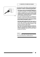
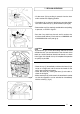
4 - INSTALLATION a) Remove the packing binding, then slide the packing off the machine, lifting it upwards (see fig.1). b) Checking the machine identification - after removing the packing, ensure the apparatus you have received is exactly as ordered, checking the specifications indicated on the invoice or the delivery note are the same as those written on the plate.
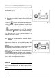
5 - CONNECTION TO POWER SUPPLY MAINS Fig. 3 For your personal safety, before inserting the plug into the electrical outlet, as previously explained in paragraph 4, carefully read the following precautions: - The electrical safety of the ICE FROST MANUAL 2.2 slush machine can only be achieved if the machine is properly connected to an efficient grounding system, in compliance with current national safety standards.
6 - CONNECTION DIAGRAM The diagram in fig. 4 shows the sequence for the connection of a CO2 cylinder to the ICE FROST MANUAL 2.2 (the said cylinder is not supplied as part of the machine’s kit). Description: (A) Ice Frost Manual 2.2 (B) CO2 cylinder (not supplied) (C) Pressure reduction unit (supplied with the machine) (D) Connection hose (supplied with the machine) Fig.
7 - REFILLING OPERATIONS - Lift the cover (G) by pushing it upwards from the front until it reaches the stopping position. - Lift the lever (H) as shown in the figure to vent the airtight tank and to allow the cap (I) to be removed (see fig. 6). Fig. 6 - Remove the cap (I) by rotating it anticlockwise and pulling it upwards, as shown in figure 7. - Pour the fizzy drink into the tank until it reaches the maximum level (8 litres). Each tank has a MINIMUM and a MAXIMUM level mark (see fig. 8). Fig.
8 - START-UP OPERATIONS Ice Boom Fizz is fitted with a multifunctional control panel shown below (fig. 10). 8.1 - Explanation of the controls and their use (manual mode) a) Switch on the control panel at the main switch (M). b) Each tank is managed by 2 buttons which are activated as follows: - button (N) - the is used to activate the mixer components; Fig.
- Press down the “MODE” button until the characters for the hour and the minutes appear on the display and the LED for the symbol starts flashing. - Press the button (O) until the hour you wish to set appears (e.g. 22). - Press the “MODE” button to confirm the hour set. - The ‘minutes’ characters will now begin to flash on the display. - Press the button (until the minutes you wish to set are displayed (e.g. 30). - Press the “MODE” button to confirm the minutes set.
Both functions have now been programmed to start automatically. When the red LED next to the button (O) lights up, this means the functions are running in the automatic mode. To switch from automatic to manual mode, press again the button (O) (the relevant red LED will go out, thus confirming that the machine is set to be operated manually). 8.3 - Variations in the time display (twenty-four or twelve hour clock) and the temperature display (°C or °F) The electronic system in the Ice Frost Manual 2.
9 - DEVICES FOR THE PROTECTION OF PERSONNEL AND THE MACHINE When the machine is started up with the main switch (as mentioned in the previous paragraph), the CO2 will begin to enter the relative tanks until it reaches the maximum designated pressure. A safety mechanism will ensure the pressure inside the tanks never exceeds 0.3 bar. The gauge (P) ensures the pressure inside the tanks is continually monitored (fig. 11). Fig.
10 - USING THE ICE FROST MANUAL 2.2 a) To dispense the product, position the cup underneath the tap (Q) and lower the lever (R) very slowly (fig. 12). b) Adjusting the consistency Use the dial (S) as shown in fig. 13 to alter the consistency of the ice slush. Fig. 12 When the dial is turned clockwise, the product becomes less dense. When the dial is turned anticlockwise, the product becomes denser.
11 - CLEANING AND SANITATION PROCEDURES Fig. 14 To ensure the apparatus always works well and complies with the hygiene and sanitary standards in force in the country of use, it is essential to carry out the cleaning and sanitation procedures for the ICE FROST MANUAL 2.2 models frequently and carefully, as explained in detail in the following instructions. The Ice Frost Manual 2.2 can be cleaned and sanitised with 2 different methods, both of which are efficient.
e) Lift the unit and remove it from its seating (as shown for the other tap) without removing the tap (U) completely. Connect a discharge hose (V) long enough to reach a discharge point to the outlet tap (fig.18). f) Turn on the water flow to rinse the tank carefully. g) Reposition the tap in its seating, ensuring it is inserted fully. Fill the tank with water, using the CIP system, until the water level in the tank reaches the cover, then turn off the water (fig. 19). Fig.
button j) Switch on the mixer components with the and allow the sanitising solution to move around until it changes colour. The change in colour indicates the internal components have been completely sanitised. k) Lower the tap lever to empty the tank of all the solution (fig. 22). Fig. 22 l) Lift the unit and remove it from its seating (as shown for the other tap) without removing the tap (U) completely (fig. 23). Fig.
p) Remove the cap (T) fitted with the CIP device (fig. 26). q) Remount the normal cap (I). r) As soon as all the cleaning procedures are complete, repeat the same operations, in the same order, for the other tank/s. 11.2 - Cleaning and sanitising operations using the normal method (MONTHLY) Fig. 26 Attention !! Unlike with the cleaning operations using the CIP method, the following cleaning operations must be carried out with the machine disconnected from the electricity supply, as described earlier.
f) Remove the tap from its seating by pressing the two clamping tabs (fig. 31). g) Dismount the tap by pushing the body (B1) downwards, then slide the lever (R) out of its seating (fig. 32). Wash all the individual parts carefully with hot water and washing-up liquid, rinse it well and proceed with the reassembly. Fig. 31 h) Separate the tank from its cover, undoing the fasteners (D1) by pulling them upwards as shown in fig. 33. Fig.
j) Loosen the fastening knob (F1) by turning it in the direction indicated by the arrow (left-hand screw thread) and proceed to extract the scraping spiral (G1) and the washers (H1) and (I1). Clean all the individual parts carefully (fig. 35). k) Clean the drip surface (J1) and the evaporator (K1) properly (fig. 36). l) To re-assemble the mixer unit, proceeding as follows (fig.
n) Remount the tap, remembering to spread the Vaseline over both the seating and the sealing strips (fig. 39). o) Dismount the drip collector tray (M1), pulling it downwards then out (fig. 40). Wash all the parts carefully and proceed to reassemble them, following the procedure outlined above and remembering to reinsert the condensation discharge hose (N1) into its seating. Fig. 39 M1 N1 Fig.
O1 12 - SPECIAL MAINTENANCE Attention !! To ensure the cooling system performs well, it is essential to clean the condenser filter regularly. As explained earlier in paragraph 9, an audio alarm, accompanied by the message "FILT" on the control panel display, indicates the filter is blocked and must be cleaned, otherwise the machine will stop automatically. Proceed as follows: - disconnect the machine from the power supply; - unscrew the knob (O1) so that the rear panel (P1) is released (fig. 41).
SPARE PARTS SPARE PARTS ORDERING Request the spare parts by indicating: A) B) C) D) E) type of the machine voltage of the machine serial number table number position number MOD. ICE FROST MANUAL 2.
TAV. 1 ICE FROST MANUAL 2.
It is strictly forbidden to reproduce this instruction manual or any part thereof.