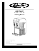
® ICE FROST Post-Mix and Pre-Mix Training Manual Release Date: May 18, 2005 Publication Number: TP01080 Revision Date: N/A Revision: A Visit the IMI Cornelius web site at www.cornelius.com for all your Literature needs.
ICE FROST POST-MIX AND PRE-MIX TRAINING MANUAL The products, technical information, and instructions contained in this manual are subject to change without notice. These instructions are not intended to cover all details or variations of the equipment, nor to provide for every possible contingency in the installation, operation or maintenance of this equipment.
TABLE OF CONTENTS Important Warnings and Advice . . . . . . . . . . . . . . . . . . . . . . . . . . . . . . . . . . . . . . . . . 1 Technical Data . . . . . . . . . . . . . . . . . . . . . . . . . . . . . . . . . . . . . . . . . . . . . . . . . . . . . . . . 1 Plate data . . . . . . . . . . . . . . . . . . . . . . . . . . . . . . . . . . . . . . . . . . . . . . . . . . . . . . . . . 1 Transportation Indications . . . . . . . . . . . . . . . . . . . . . . . . . . . . . . . . . . . . . . . . . . . . . .
Special Maintenance . . . . . . . . . . . . . . . . . . . . . . . . . . . . . . . . . . . . . . . . . . . . . . . . . . 21 Restricted Air Flow Alarm . . . . . . . . . . . . . . . . . . . . . . . . . . . . . . . . . . . . . . . . . . . . 22 Electronic Monitoring . . . . . . . . . . . . . . . . . . . . . . . . . . . . . . . . . . . . . . . . . . . . . . . . . Electronic Bowl Monitoring and Safety System . . . . . . . . . . . . . . . . . . . . . . . . . . . . Pressure and Level Control Card General Features .
Ice Frost Training Manual IMPORTANT WARNINGS AND ADVICE This instruction manual represents an integral part of the equipment and must be kept readily available for use. Read the warnings contained herein carefully before installing and using this equipment.
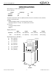
Ice Frost Training Manual SPECIFICATIONS Bowl Capacity: 2.1 Gallon (8 liter) per bowl Electrical Ratings: Voltage Amperage 115V/60Hz 220V/60Hz 230V/50Hz Fuse 13.8 8.0 6.7 20 10 10 Installation Requirements: Allow 8” (200mm) minimum clearance around back and 4” (100 mm) clearance around both sides. Post-Mix: Carbonated Water Supply = 1/4” (6.5 mm) barb connection BIB Pump and Rack - 2 Pump - 1/4” (6.
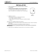
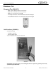
Ice Frost Training Manual INSTALLATION 1. 2. Remove the equipment from the packing, then slide it off upwards (see FIGURE 2). Checking the machine identification after removing the packing, you must check that the equipment you have received is exactly as you ordered, making sure the specifications indicated on the invoice or the delivery note are identical to those on the data plate. FIGURE 2 3.
Ice Frost Training Manual SITE ASSESSMENT SECTION WATER SYSTEM • Filters: Coarse? ____ Taste/Odor? ____ Scale Inhibitor? ____ • Is water main ½ inch I.D. minimum? ____ • Pressure Static? ____ • Pressure Flowing?____ • Length of run? ___ • Shut off valve? ____ • Back flow prevention? ____ • Is water softened? ____ • Is water line connected to a water heater? ____ • Perform water test to insure that the minimum flow and pressure requirements are met or exceeded.
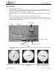
Ice Frost Training Manual TEST SECTION Water pressure& volume test: Estimate the water usage of all equipment connected to the water delivery system (e.g.Intellicarb = 125 G.P.H. a two Fl. Pinnacle = 100 G.P.H. Total = 225 G.P.H.) Select the 13/64 orifice to insure that you can supply more then the 225 G.PH. Required to operate both units. Connect the IMI Cornelius water test device (FIGURE 3) to the supply line that will be connected to the unit.
Ice Frost Training Manual ELECTRICAL TEST Receptacle Test (FIGURE 7) • Open ground - Ground contact not connected. • Open neutral - Neutral contact not connected. • Open hot - Hot contact not connected. • Hot and ground reverse - Hot and Ground contacts interchanged. • Hot and Neutral reversed - Hot and neutral contacts interchanged. FIGURE 7 Volt/Ohm Meter (FIGURE 8) Check the following: • Voltage at receptacle. • Correct voltage range. Used to troubleshoot the unit and components.
Ice Frost Training Manual CONNECTION DIAGRAMS Ice Frost Generic (Pre-mix) The diagram shows the sequence for the connection between the ICE FROST GENERIC PRE to an existing pre-mix system. FIGURE 9 Description: 1. Pre-mix product 1 inlet. 2. Pre-mix product 2 inlet. 4. Inlet for CO2 (coming from the pressure reducing valve, 12 psi). 5. CO2 gas cylinder. 6. 7. Operating pressure gauge. 8. 9. 10. 11. Gas cylinder pressure gauge. Pre-mix product 1 container. Pre-mix product 2 container.
Ice Frost Training Manual Ice Frost Generic (Post-mix) The diagram shows the sequence for the connection between the ICE FROST GENERIC POST to an existing post-mix system. FIGURE 10 Description: 1. Syrup 1 inlet. 2. Syrup 2 inlet. 3. Soda water inlet. 4. Inlet for CO2 45 to 60 psi. 5. CO2 gas cylinder. 6. 7. 8. 9. 10. 11. 12. 13. 14. 15. 16. 17. 18. Operating pressure regulator for carbonation unit. Carbonation unit operating pressure gauge. Unit and BIB operating pressure gauges. Pressure regulator.
Ice Frost Training Manual PUMP INSTALLATION • As indicated on the pump, the outlet port is to be mounted up. • Pumps are to be mounted at the same level or higher than the B-I-B. The best choice is to have the pump above the B-I-B. • INLET tubing from the B-I-B to the pump use; 3/8” I.D. [10mm] minimum, heavy wall (1/8” [3mm]) clear, NSF listed vacuum tubing. Inlet tubing should not have excessive length.
Ice Frost Training Manual BOWL LOADING OPERATIONS ICE FROST GENERIC (PRE-MIX) WARRNING: If the unit runs out of product and is turned off and turned back on without a new (full) product tank installed the sensor will look for product for 4 minutes. During this 4 minute period CO2 will be purged from the bowl. • Switch the machine’s main switch to the ON position (1). • Put the switch (A) into the ON position (1) see FIGURE 11, switch A. Controls the flow of the product in the bowls.
Ice Frost Training Manual Brix and Ratio Procedure • Now pull the post-mix valve out further and tighten the 1/8 inch (8mm) nut (FIGURE 12, A) using the socket wrench. • Remove the post-mix valve’s nozzle and apply the syrup separator (B), then the ratio cup (C) and push the micro switch on the valve (A) until both the soda water and the syrup run into the measuring cup separately (FIGURE 13).
Ice Frost Training Manual PROGRAMMING ELECTRONIC TOUCH PAD To lower/open the control cover, use a coin or other object to turn the keyless lock to the horizontal position, in order to open access the operating panel (controls are located on the right side of the unit). Auger ON/OFF Button Main Power Switch • Turns unit ON. Fo o • Selects 12/24 time clock or /C temperature display when turned ON while simultaneously depressing the auger button.
Ice Frost Training Manual Setting COLD Timer (Night Setting) 1. 2. 3. Turn the power switch ON. Make sure the “AUTO TIMER” is OFF (i.e. light on button is not lit). Press the left hand “Auger ON/OFF” button ON. Press and hold the “PRESS TO SELECT FUNCTION” button until you hear a long beep and the LED, “Cold” and the “AUTO TIMER” clock light begins to blink. 4. Press the “AUTO TIMER” clock button to set the unit to COLD mode and then press the “PRESS TO SELECT FUNCTION” button to save the setting. 5.
Ice Frost Training Manual Viewing the Bowl Temperature 1. 2. Turn ON the auger on the side that you want to display the bowl temperature (press the “AGER ON/ OFF” button). Press the “PRESS TO SELECT FUNCTION” button until the “Cold” LED is lit. The display will now show the current bowl temperature in either oF or oC as applicable. DISPENSING PRODUCT 1. To dispense the product, place the cup beneath the dispensing valve and pull the lever very gently (FIGURE 15). FIGURE 15 CONSISTENCY ADJUSTMENT 2.
Ice Frost Training Manual ALARMS Safety Probe Alarms (only for ICE FROST GENERIC Pre-mix) You will remember that the monitoring of the safety probes’ conditions (satisfied/ not satisfied) is only active during the bowl loading phase. It follows, then, that a lack of liquid in the tanks during the nonloading phases will not be signalled.
Ice Frost Training Manual “FILTER CLEANING” Alarm A filter cleaning alarm will activate when the system is running HOT due to insufficient internal air circulation. When this occurs a “Filtr” message will appear on the touch pad LED display readout and an intermittent tone will also sound to alert the operator of this condition. The “Filtr” message will appear when the alarm activates (a beeping sound every 4-5 seconds).
Ice Frost Training Manual BI-ANNUALLY CLEANING AND SANITATION ATTENTION: The cleaning operations must be performed with the machine disconnected from the power supply. 1. 2. Empty the bowl of any remaining product and switch off the main switch see FIGURE 14 on page 12. Remove the cover (B) - FIGURE 30. 3. Extract the quick couplings (C2) / (F2) - (FIGURE 17, FIGURE 18, and FIGURE 19). FIGURE 18 FIGURE 17 FIGURE 19 4. Disconnect the probe fastenings (FIGURE 17, FIGURE 18, and FIGURE 19). 5.
Ice Frost Training Manual 6. Slide the locking bar (FIGURE 22) out so that the bowls are fully released. Unlock relief valve on the bowl lid cap and remove (FIGURE 20). FIGURE 21 FIGURE 22 7. Unscrew the knobs (FIGURE 23) so the bowls can be lowered slightly, open the tap to remove any remaining liquids and then pull it forward from its seating. FIGURE 23 Publication Number: TP01080 - 18 - © 2005, IMI Cornelius Inc.
Ice Frost Training Manual 8. Remove the tap from its valve body, pressing the two clamping wings at the same time (FIGURE 24) and pushing upwards. 9. Remove the tap, holding the body pressed downwards, then slide the lever out of the valve body. Wash all the parts thoroughly with hot water and mild detergent, rinse them well, and replace them. FIGURE 24 10. Separate the bowl from its cover, releasing the fastening by pulling them upwards and rotating them a quarter turn, as shown in FIGURE 25.
Ice Frost Training Manual 12. Unscrew the fastening knob (A) clockwise as the direction indicated by the arrow (threading to the left) and extract the spiral scraper (C) and the seals (B) and (D). Clean the individual parts thoroughly (FIGURE 27). C D B A FIGURE 27 13. Clean the drip tray (A) and the evaporator (B) (FIGURE 28). 14. Replace the mixing unit as follows: • Dampen the sealing strip (FIGURE 27, D) and insert it into its seating.
Ice Frost Training Manual SPECIAL MAINTENANCE ATTENTION: To guarantee peak cooling system performance, the routine cleaning of the condenser filter is essential. As explained earlier, an audible signal accompanied by the word FILT appearing on the control panel display, will warn the operator when the filter is clogged and so must be cleaned before the machine comes to an automatic stop. • Disconnect the machine from the power supply; • Unscrew the nut (C in FIGURE 30).
Ice Frost Training Manual RESTRICTED AIR FLOW ALARM To protect the entire cooling system, the Ice Frost drinks maker is fitted with an electronic system which issues an acoustic warning signal in the event of insufficient ventilation or if the condenser filter is clogged. In addition to this, the words FILT and then ERR will appear on the control panel display. FIGURE 33 If the operator does not intervene when the signal is issued, restoring normal working conditions (i.e.
Ice Frost Training Manual ELECTRONIC MONITORING ELECTRONIC BOWL MONITORING AND SAFETY SYSTEM The diagram shows the electronic pressures and levels management system: 1. 2. 3. 4. 5. Safety valve. Monitoring card for maximum limit exceeded probes. Bowl 1 overpressure discharge relief valve solenoids. Bowl 2 overpressure discharge relief valve solenoids. 6. 7. Pressure and levels monitoring card. CO2 pressure switch (not shown). CO2 inlet solenoid valve.
Ice Frost Training Manual PRESSURE AND LEVEL CONTROL CARD GENERAL FEATURES Via a micro-controller, the µZ4LP allows the operator to manage the levels and the relative safety devices linked to the two cold drink bowls. An electronic pressure switch card (amplified, linearized, and compensated) is provided for monitoring the pressure of the gas used in the post-mix phase of the said drink. The Electronic Pressure Switch Card will have the following features: • Independent level control for each bowl.
Ice Frost Training Manual OFF CONDITION In this condition, the electronic control is not connected to the power supply. To connect the ECB to the power supply, the main system switch must be put in the ON position.
Ice Frost Training Manual Managing the Bowl Levels When one of the two level probes fails to detect the presence of liquid in the bowl, the Fill solenoid valve is activated to refill the correct level.
Ice Frost Training Manual NOTE 1: the same intervention methods are applied when the safety probe is uncovered after the solenoid valve has been activated. NOTE 2: the 3-second software filter activated when it detects the safety probe is uncovered and the relevant signal have been introduced to prevent the probe recognizing the “tank-bowl” conduit as “empty” when there is residual gas in it.
Ice Frost Training Manual WIRING DIAGRAM VFCB (PRE-MIX) 115V/60HZ FIGURE 39 Publication Number: TP01080 - 28 - © 2005, IMI Cornelius Inc.
Ice Frost Training Manual VFCB (POST-MIX) 115V/60HZ FIGURE 40 © 2005, IMI Cornelius Inc.
Ice Frost Training Manual VFCB (PRE-MIX) 230V/50HZ FIGURE 41 Publication Number: TP01080 - 30 - © 2005, IMI Cornelius Inc.
Ice Frost Training Manual VFCB (POST-MIX) 230V/50HZ FIGURE 42 © 2005, IMI Cornelius Inc.
Ice Frost Training Manual TROUBLESHOOTING NOTE: The following procedures must be performed by a qualified service technician.
Ice Frost Training Manual Problem The machine over-freezes making the auger movement slow or stopped Possible Cause • The product Brix/ratio is too low Solution • Check the product Brix/ratio and correct • The screw setting for the product consistency control system is set too far toward the “+” position • The limit switch arm is bent away from the gearmotor and prevents contact • The level of the product in the bowl is too low, exposing the auger • The compressor PC board contacts don’t open • Rese
Ice Frost Training Manual Problem Possible Cause Solution Cap is leaking • The nut is loose • Tighten the nut Bowl not refilling • Out of syrup • Replace • Out of CO2 • Replace • Valves are shut off or blocked • Open • Foam covering probes • Wait • Fill Switch in off position • Turn on • Defective syrup pressure switch • Replace • Defective CO2 shut off • Replace Bowl is overfilling • Bad Pressure and Levels Card • Replace the card CO2 leaking from back of unit • Proper function of
Ice Frost Training Manual Does unit have enough clearance Filter dirty Yes Is filter dirty or restricted Yes Clean filter or condenser Yes Are fuses OK Yes Is high pressure cutout tripped No Reposition unit Is power switch ON Unit not running No No Turn unit ON Replace fuses Yes Check fan and condenser CO2 Yes Test sold out switch and replace if defective Syrup Yes Test sold out switch and replace if defective Yes Bowl not refilling Are syrup, H2O, and CO2 satisfied Yes Is fill
Ice Frost Training Manual Auger making noises Machine ON but auger not turning Is bowl seal in place Yes Yes Is shaft seal lubed and intact Yes Is the auger assembled correctly No No No Reposition seal Replace and lube seal Correct (check gear pin) Is auger switch ON Yes Is motor turning No Yes Check and replace shear pin, if necessary No Is there voltage at motor plug Turn it ON Yes Test and replace motor if defective Yes Incomplete circuit or bad board No Is there voltage at t
Will not freeze Is the compressor running Yes Is the Amp draw correct Is the Brix correct Yes Yes Is the viscosity correct Yes No No Adjust Brix Set Viscosity Call Service No No Is unit in Freeze mode No Enter Freeze mode Yes Low High No No Is the discharge line hot Is the fan on No No No Recover refrigerant, repair leak, and recharge Repair or replace Call Service Is there voltage to the start capacitor Yes Is the condenser plugged Yes Replace start components Yes Free
IMI Cornelius Inc. www.cornelius.