® CONTINUOUS FLOW ICEMAKER 500, 700, 1000, 2000 - Series Service Manual Release Date: May 27, 2004 Publication Number: 630460174SER Revision Date: September 24, 2008 Revision: D Visit the IMI Cornelius web site at www.cornelius.com for all your Literature needs.
CONTINUOUS FLOW ICEMAKER SERVICE MANUAL The products, technical information, and instructions contained in this manual are subject to change without notice. These instructions are not intended to cover all details or variations of the equipment, nor to provide for every possible contingency in the installation, operation or maintenance of this equipment.
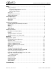
Continuous Flow Icemaker Service Manual Safety . . . . . . . . . . . . . . . . . . . . . . . . . . . . . . . . . . . . . . . . . . . . . . . . . . . . . . . . . . . . . . . .1 Safety Instructions . . . . . . . . . . . . . . . . . . . . . . . . . . . . . . . . . . . . . . . . . . . . . . . . . . .1 Read and Follow all Safety Instructions . . . . . . . . . . . . . . . . . . . . . . . . . . . . . . . .1 Recognize Safety Alerts . . . . . . . . . . . . . . . . . . . . . . . . . . . . . . . . . . . . . . . . . .
Continuous Flow Icemaker Service Manual Publication Number: 630460174SER - ii - © 2004-2005, IMI Cornelius Inc.
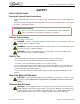
Continuous Flow Icemaker Service Manual SAFETY SAFETY INSTRUCTIONS Read and Follow all Safety Instructions Read and follow all safety instructions in this manual and on the machine (decals, labels, and laminated cards). Read and understand all applicable OSHA (Occupation Safety and Health Administration) safety regulations before operating the machine. Recognize Safety Alerts This is the safety alert symbol.
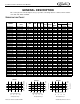
Continuous Flow Icemaker Service Manual GENERAL DESCRIPTION This section gives the Unit description, theory of operation, and design data for continuous flow icemaker series 500, 700, 1000, and 2000.
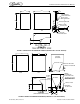
Continuous Flow Icemaker Service Manual 25.00 14.50 1.38 1.75 INLET 3/8 FLARED WATER COOLED ONLY OUTLET 3/8 FLRE WATER COOLED ONLY 24.50 DRAIN 3/8 ID TYGON TUBE 10.15 WATER IN 1/4 FLARE ELECTRIC 7/8 DIA 1.50 1.81 FRONT 2.12 2.50 SIDE 1.19 BACK VIEW AIR OR WATER COOLED FRONT ICE DISCHARGE 3.50 FIGURE 1. SERIES 500 & 700 DIMENSION DRAWING (SHIPPING WT. 160 LBS. APPROX). 24.00 22.00 BACK VIEW (AIR COOLED) 27.00 ELECTRICAL 7/8” DIA. WATER UB 1/4” MALE FLARE DRAIN 3/8” ID TYGON TUBE 2.25 2.25 0.
Continuous Flow Icemaker Service Manual 18.13 30.00 WATER IN ELECTRICAL 7/8 DIA. 28.06 23.50 AIR INLET DRAIN 3/8 I.D. TUBE 2.25 BACK FRONT 2.06 24.00 ICE DISCHARGE 9.50 2.06 20.13 3.81 FRONT 2.06 SIDE BOTTOM VIEWED FROM BOTTOM OF MACHINE FIGURE 3. SERIES WCC2001-A AND WCF2201-A DIMENSION DRAWINGS Publication Number: 630460174SER -4- © 2004-2005, IMI Cornelius Inc.
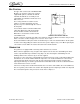
Continuous Flow Icemaker Service Manual BIN CONTROL The type of bin control used on all WCC & WCF Models is an electronic control. The control is supplied with power to terminals X1 and X2. Terminals X3 and X4 are a normally closed switch which open when the thermostat sensor bulb senses ice. The sensing element is located in a 5/16” stainless steel tube which hangs from the dispense tray cover down through the center of the drop tube. To test switch, start the icemaker and block the outlet tube.
Continuous Flow Icemaker Service Manual CLEANING AND SANITIZING ICEMAKER CLEANING AND SANITIZING PROCEDURES Do not use any of the ice made during cleaning operations. Clean and sanitize ice storage area when cleaning icemaker. 1. 2. 3. 4. Turn machine off. Shut off water supply. Remove ice from storage bin. Mix approved cleaner (2 gallons as directed). Recommended cleaner: Nu-Calgon liquid ice machine cleaner. Mixture: 3-1/3 ounces per gallon of water. WARNING: Cleaner must be safe for stainless steel.
Continuous Flow Icemaker Service Manual SEMI-ANNUALLY Semi–Annually in addition to all previously established service procedures perform the following: 1. 2. 3. 4. 5. 6. 7. Check for water leaks in tube connections, water fittings and lower icemaker water seal. Check drain tubes for clogs and aged tubes. Replace if tubes are stained or brittle. Check for signs of condensation. Clean where necessary and replace insulation properly. Check safety circuits for proper operation. Check refrigeration system.
Continuous Flow Icemaker Service Manual WATER LEVEL CONTROL HOW WATER LEVEL CONTROL WORKS When water is introduced through the inlet fitting the float rises. the float pushes against a lever which in turn forces the poppet assembly against the inlet fitting valve seat which seals the water off. Before the water inlet is sealed the safety switch is operated. In the event of a water failure the float would drop down and operate the safety switch to shut off the machine.
Continuous Flow Icemaker Service Manual ELECTRICAL FIGURE 6. SCHEMATIC AND WIRING DIAGRAM WCC2001-A AND WCF2201-A FIGURE 7. SCHEMATIC AND WIRING DIAGRAM WCC500-A, WCC500-W, WCC700-A, WCC700-W, WCF510-A, WCF510-W, WCF710-A, & WCF710-W © 2004-2005, IMI Cornelius Inc.
Continuous Flow Icemaker Service Manual FIGURE 8. SCHEMATIC AND WIRING DIAGRAM WCC701-A, WCC701-W, WCC1001-A, WCC1001-W, WCF711-A, WCF711-W, WCF1101-A, & WCF1101-W FIGURE 9. SCHEMATIC AND WIRING DIAGRAM WCF1101R, WCC1001R, WCF1102R, & WCC1102R Publication Number: 630460174SER - 10 - © 2004-2005, IMI Cornelius Inc.
Continuous Flow Icemaker Service Manual FIGURE 10. SCHEMATIC AND WIRING DIAGRAM WCC502, WCC702, WCC1002, WCF512, WCF712, & WCF1102 FIGURE 11. SCHEMATIC AND WIRING DIAGRAM WCC2001-R AND WCF2201-R © 2004-2005, IMI Cornelius Inc.
Continuous Flow Icemaker Service Manual Air Temperature REFRIGERATION SYSTEM 50° 60° 70° 80° 90° 100° 40° 162 188 214 245 275 309 Thermostatic Expansion Valve NO Adjustment. +/- 10 lbs.
Continuous Flow Icemaker Service Manual CONDENSER MODULATING VALVE The reason for using a water modulating valve is to supply the correct amount of water to the condenser. and to maintain a proper operating pressure to refrigeration system high side. The flow of water through the valve is increased as the high side pressure rises and is decreased as high side pressure lowers.
Continuous Flow Icemaker Service Manual CONDENSER MODULATING VALVE REMOVAL 1. 2. 3. 4. 5. 6. 7. 8. 9. Disconnect power to unit, then shut off water supply to condenser and evacuate refrigerant from system. Remove inlet water line from Condenser Modulating Valve. Also remove tube from high side refrigerant line. Remove Condenser Modulating Valve and bracket from unit. Remove valve from bracket. Replace Condenser Modulating Valve by reversing Steps 2 through 4. Then pull system into vacuum.
Continuous Flow Icemaker Service Manual MOTOR CHECK The resistance readings on the winding will be between 5 to 25 ohms. A meter capable of these low readings must be used. The start relay cover must be removed. If no continuity on start or run winding test, replace gearmotor. If continuity on grounded motor test, replace gearmotor. START RELAY 1. 2. Check between “2” and “4” on relay (with relay unplugged). If there is continuity replace the relay, as the relay contacts should be open.
Continuous Flow Icemaker Service Manual INSTALLATION AND SHAFT SEAL REPLACEMENT 500 1. 2. 3. 4. Place shaft seal locator seat over gear motor output shaft, embossed side down, and push down until shaft seal seat rests flush on top of gear motor. Place rubber coated ceramic seal (important: ceramic face up) over output shaft and push down until seal rests on top of the shaft seal seat. (Lubricate rubber on ceramic seal with rubber lubricant.
Continuous Flow Icemaker Service Manual INSTALLATION AND SHAFT SEAL REPLACEMENT 700 & 1000 1. 2. 3. 4. Place shaft seal locator seat and shaft seal mount over gearmotor output shaft and push down until shaft seal seat and shaft seal mount rest flush on top of gearmotor. Place rubber coated ceramic seal (important: ceramic face up) over output shaft and push down until seal nest in recess of shaft seal mount. (lubricate rubber on ceramic seal with rubber lubricant).
Continuous Flow Icemaker Service Manual OVERLOAD CHECK Using a volt–ohmmeter check the continuity across the overload, contact #1 and #3. If none, wait for unit to cool down and try again. If still no continuity, the overload protector is defective and should be replaced. FIGURE 18. OVERLOAD CHECK COMPRESSOR CHECK The resistance readings on the windings will be between 0.25 to 10.00 ohms, a meter capable of these low readings must be used. 1. 2. 3. 4. Check between “C” and “R.
Continuous Flow Icemaker Service Manual SAFETY CONTROLS Your icemaker unit has several safety and control devices incorporated into its design. WARNING: None of the below described devices should ever be “bypassed” to allow the unit to function. The safety and control system shut–off devices are: 1. 2. 3. 4. 5. 6. 7. Low water shut off reed switch located in icemaker float assembly. (Automatic reset type.) Gearmotor thermal overload, manual reset type (red button on motor).
Continuous Flow Icemaker Service Manual GUIDE TO GOOD ICE CUSTOMER COMMENTS CHECK ICEMAKER LOCATION CONDITIONS FIRST “It runs but the ice is too soft.” Proper air flow for condensing system. “The icemaker is not producing enough ice.” Location too close to high units such as coffee urns, deep fryers, grills, etc. “The ice is too wet.” Supply water conditions Water too warm (above 90 o F). Water artificially softened above 262 ppm sodium chloride.
© 2004-2005, IMI Cornelius Inc. - 21 - Open valve Evacuate and recharge system. Clean condenser. Non-condensible in system. Condenser fan not running. LAC not operating properly (minimum discharge pressure 180 lbs.). Check for leaks. Replace LAC valve, evacuate and recharge system. Remote condenser units only Replace dryer. Evacuate and recharge system. Plugged liquid line dryer. Replace valve. Evacuate and recharge system. Check gears in gearbox. No Check if auger is turning.
Continuous Flow Icemaker Service Manual Publication Number: 630460174SER - 22 - © 2004-2005, IMI Cornelius Inc.
IMI Cornelius Inc. www.cornelius.